Related Articles


The Drilling Process and the Borehole Environment
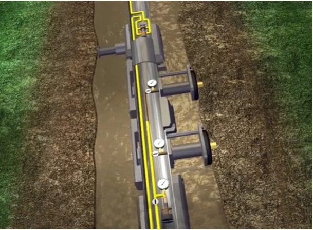
When a drill bit first penetrates a permeable formation, the drilling mud filtrate invasion process almost always occurs, at least to some extent (Animation 1).
In the more usual overbalanced situation where the pressure in the drilling mud column exceeds the formation pressure, fluid from the drilling mud will be forced into the formation, provided it has some permeability, normally leaving a deposit of mud cake on the borehole wall.
The radius of the drilling mud filtrate invasion typically ranges up to 4 feet around the borehole, but can move out beyond 8 feet in some circumstances, such as a high differential pressure between the wellbore and the formation. The shape of the invaded zone is usually assumed to be cylindrical around the borehole, and to contain water with a resistivity equal to that of the mud filtrate resistivity. The mud filtrate resistivity, Rmf, is regularly measured at the surface by running a drilling mud sample through a filter press. Figure 1 details the industry symbols and nomenclature convention for fluid invasion around a wellbore.
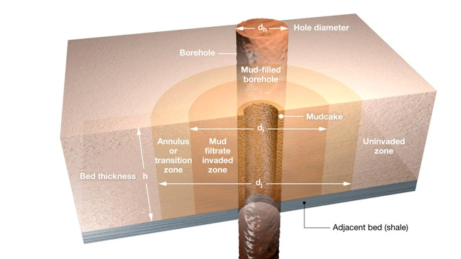
The flushed zone is defined as that zone around the borehole circumference where the pores contain mud filtrate. The wellbore transition zone contains a mixture of mud filtrate and the original formation water, together with any residual hydrocarbons remaining after the mud filtrate invasion process. The flushed zone is significant because it tends to affect the readings of most logging while drilling (LWD) and wireline logging tools. It also complicates the quest for valid formation fluid recovery from formation tester sampling tools (Figure 2). The radial extents of each of the flushed and invaded zones are not known until well logs, either LWD or wireline, have been run. Consequently, resistivity measurements with a range of different investigation depths, such as those acquired by array induction and laterolog resistivity tools, are needed to delineate these zones and compensate for their effects on many of the well log measurements.
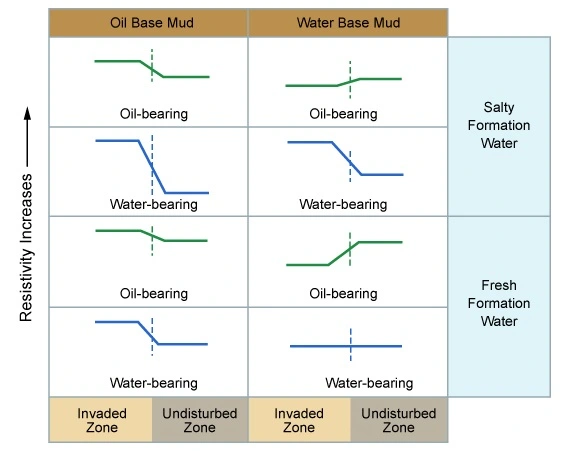
Depending on the type of drilling mud used (oil or water base mud with a certain salinity), the relative values of the mud filtrate resistivity, Rmf, and formation water resistivity, Rw, the invasion process may generate a radial resistivity profile that either increases or decreases with distance away from the borehole wall. In the unusual situation that the formation water and the drilling mud filtrate have exactly the same salinity, the profile will be unaffected.
Figure 3 illustrates a number of such scenarios.
It is important to distinguish between the resistivity of the fluids within the pore spaces and the resistivity of the rock matrix fluid system itself. The terms used in Table 1 below are used by petrophysicists and others involved in well log evaluation work.
| Table 1: Nomenclature and Symbols for Various Borehole Environment Resistivities | ||||
|---|---|---|---|---|
| Name of Zone | Dimension | Fluid Content | Fluid Resistivity | Rock Resistivity |
| Bed | h | — | — | — |
| Adjacent bed | — | — | — | Rs |
| Mud | — | Mud | Rm | — |
| Mud cake | dh | — | — | Rmc |
| Flushed, or invaded, zone | di | Mud filtrate and residual hydrocarbons | Rmf | Rxo |
| Transition zone | dj | (Formation water and mud filtrate mixture) and hydrocarbons | — | — |
| Uninvaded, virgin zone | — | Formation water and hydrocarbons | Rw | Rt |