Related Articles


Directional Drilling Terminology
For a GeoSteering Team to work effectively with the Directional Driller and other geonavigation specialists, they must be able to communicate in the same language, using a precisely defined terminology that leaves little room for misinterpretation between specialists from different disciplines. The following terms will be useful in maintaining good communication between the GeoSteering Team and the Specialists at the wellsite.
Accelerometer – A device mounted inside MWD, wireline, and survey tools to measure the acceleration of a tool in a particular direction, thus detecting changes in direction with respect to the Earth’s gravity.
Actuator – A hydraulic component in the MWD transmitter that creates a pressure pulse in the process of mud pulse telemetry.
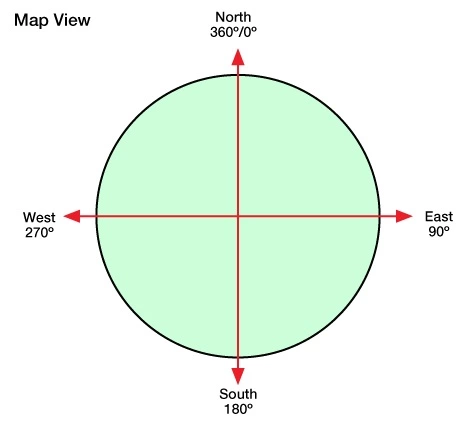
Azimuth – Direction of drilling expressed as a compass bearing ranging from 0 -360 degrees, without respect to Vertical Section Plane, Inclination, etc., as shown in Figure 1. Azimuth can be obtained as part of a directional survey.
Azimuthal Deviation – The difference in azimuth between actual and planned well paths, typically expressed at a specific measured depth.
Bit Whirl – A deviation in bit rotation around the bit’s geometric center.
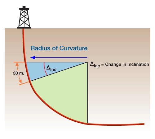
Build Up Rate (BUR) – The rate at which the well builds inclination, expressed as  of Measured
Depth (or  ).
).  (Figure 2).
Closure Distance – The shortest lateral distance between the well’s surface location and a point in the wellbore, as shown by the blue line in Figure 3.

Closure Direction – The azimuthal direction from the surface location to a survey point in the wellpath, measured in a 360-degree (radial) coordinate system.
Course Deviation – The vertical displacement between two survey points.
Declination – The angular difference in azimuth between magnetic north and true north. The magnetic declination varies from one position on the earth to another, with changes in local magnetic fields. Declination also changes over time, usually at a regular pace of a fraction of a degree every year. This change occurs with the gradual drift of magnetic north. By convention, magnetic declination is denoted as positive when magnetic north lies east of true north, and negative when magnetic north lies west of true north.
Departure – The coordinate measured in an east-west direction to describe the map view location of a target.
Deviation – The inclination angle of the wellbore axis measured from a vertical axis.
Dip – The inclination angle which a geologic layer, sedimentary bed, or seismic reflector makes with horizontal plane.
Directional Drilling – The intentional deviation of a wellbore from the vertical, along a pre-planned course of trajectory.
Directional Survey – A process of measuring depth, inclination and azimuth to determine the true vertical depth and position of the wellbore.
Dogleg – An abrupt change in hole angle. Though doglegs are sometimes created intentionally by directional drillers, this term is most often used to describe a hole section where trajectory changes faster than anticipated or desired.
The Directional Driller will strive to limit the severity of a dogleg, which can cause such problems as:
- Deviation of the wellbore from its planned course.
- Inability to run casing through the dogleg.
- Excessive wear between the casing and the drill string.
- Sticking problems arising from the development of keyseats in the crooked section of the hole.
Dogleg Severity (DLS) – A normalized estimate of the overall curvature of the well path between two consecutive survey stations. Dogleg severity is expressed in degrees / 30 meters or degrees / 100 feet, and describes the three dimensional, cumulative change in wellbore inclination and azimuth. This information, obtained through regular wellbore directional surveys, can be considered a measure of wellbore tortuosity.
Downhole Motor – A tool positioned above the drill bit that converts hydraulic energy from the circulating drilling fluid into mechanical energy, in order to turn the bit without having to rotate the drill string.
Drift – Deviation from the vertical.
Extended Reach Well – Any well which deviates in excess of 65 degrees from the vertical, and which reaches out horizontally for a distance that is more than twice its vertical depth.
Gyroscopic Survey Tool – A survey instrument which uses a gyroscope to measure the well’s azimuth angle at each survey point.
Highly Deviated Well – A well drilled with an inclination of 30-80 degrees from vertical.
Horizontal Drilling – A directional drilling technique which causes wellbore deviation to exceed 80 degrees from the vertical, with the intent of maximizing the length of wellbore exposed to the reservoir. Wells that undulate above and below 90 degrees deviation are also classed as horizontal wells.
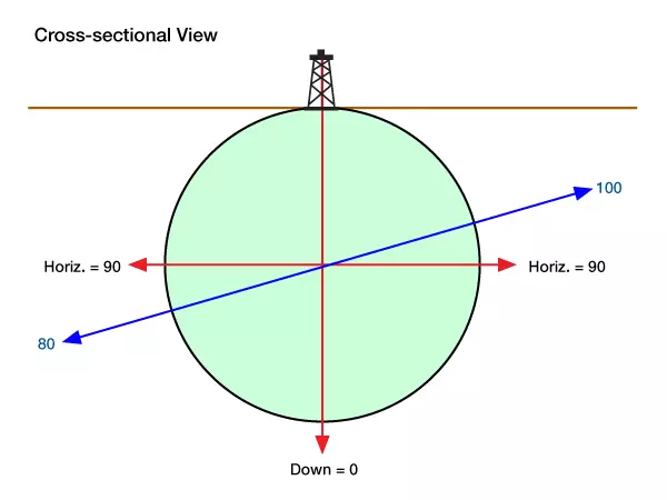
Inclination – The measure of a well’s deviation from vertical, in degrees, without respect to Azimuth, Vertical Section Plane, etc. Inclination can be measured by a pendulum-type mechanical drift indicator (only used in the vertical segment of a well), or by magnetic or gyroscopic survey tools, inertial navigation devices, wireline steering systems, or MWD tools.
By convention, 0.0 degrees of inclination describes a vertical well path, while a horizontal path is expressed as 90 degrees. Hence, 10 degrees below horizontal is 80.0 degrees, and 10 degrees above horizontal is 100 degrees. (Figure 4)
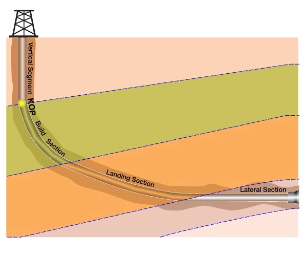
Kick-Off Point (KOP) – The point at which a vertical well is intentionally deviated by increasing inclination to create a directional or horizontal well. This point marks the beginning of the build section in a directional well, captioned in yellow in the accompanying Figure 5.
Last Chance Marker – A recognizable stratigraphic marker, usually located near the base of the build section, which serves as the basis for making course adjustments before drilling into the landing section of a horizontal well, as shown in the accompanying Figure 6.
Lateral Bore – The horizontal section of a horizontal or multilateral well.
Long Radius Well – A horizontal well characterized by a maximum build rate of 6˚ per 100 feet, and a build radius of 1000 -3000 feet. Such wells can be drilled with rotary or steerable systems for the curve and horizontal sections.
Measured Depth – The entire length of the well, as measured from the rotary table or kelly bushing.
Medium Radius Well – A horizontal well characterized by a build rate of 6˚ -20˚ per 100 feet, with a corresponding build radius of 300 -700 feet. Such wells are drilled with specially designed motors in the angle-build section, and may use rotary or steerable systems for the horizontal sections.
Minimum Curvature (Circular Arc) – A method used to derive horizontal and vertical coordinates from the values of along-hole-depth (ADH), inclination (I), and azimuth (A).
Mud Motor – A downhole motor that is hydraulically driven by the circulation of drilling fluid, and designed to rotate the bit without rotating the drill string.
Poppet Valve – A conical device on the MWD downhole assembly which extends and retracts to restrict the flow of mud, thus generating a pressure pulse.
Pressure Pulse – A momentary variation in mud pressure used to transmit data from the downhole MWD tool up to the surface. Each pulse has a value of one or zero, depending on how long the poppet valve stays open.
Proposed Direction – The azimuthal direction that a wellbore must follow to reach its target.
Radius of Curvature (ROC) – The radius of curvature (Figure 2) refers to the length of the radius of the build section, and is related to the BUR with the following formula:
| Meters | |
| Feet | |
Rate of penetration (ROP) – The speed at which the bit drills the formation.
Rotor – A hub and vane assembly which transmits torque to the main drive shaft in an MWD turbine.
Scribe Line – A reference line cut along the body of the sub or tool.
Short Radius Well – A horizontal well characterized by a build rate of 1.5° -3° per foot, with a corresponding build radius of 20 -40 feet. Such wells are drilled with specially designed deflection tools or articulated motors in the angle-build section, and use rotary tools with special drill pipe for the horizontal.
Stabilizer – A short sub equipped with blades which create an outside diameter that is equal to, or slightly smaller than the bit size. The blades are designed to support the drill string against the wall of the hole while providing a minimal restriction for the circulation of drilling fluids. In directional drilling, some stabilizers have adjustable blades which can be used to turn the direction of the wellbore. In other cases, fixed stabilizers are used to stiffen the drill string.
Stator – The stationary fluid guide of an MWD turbine, through which the rotor turns.
Survey Tool – Electromechanical or mechanical device to measure either or both azimuth angle and inclination and to record these values photographically or mechanically.
Tool Face – The relative direction of the bend in the directional assembly.
Transducer – A component of the MWD system connected to the standpipe to detect mud pressure pulses generated by the downhole MWD tool. This sensor then converts the mud pressure pulses into electrical signals which can be processed by the surface MWD computer.
Transmitter – A component of the downhole MWD tool, which converts the electrical data signal into a pressure pulse.
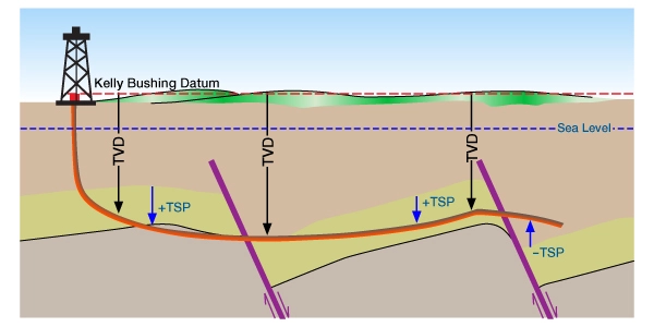
True Vertical Depth (TVD) – The vertical depth of the wellbore measured from a datum (usually the kelly bushing or derrick floor).
True Stratigraphic Position (TSP) – The position of the wellbore relative to a stratigraphic marker. The target horizon is designated as zero (0) TSP. If the well is above the marker it has a negative (-TSP); and if the wellbore is below the marker it has a positive TSP (+), as shown in Figure 6.
Vertical Section (Distance) – The horizontal distance of a well path projected on a vertical plane along a specific azimuth. The specific azimuth is usually equal to the final target azimuth. It is a one-dimensional number expressed in feet or meters. If the well path departs somewhere to either side of the vertical section plane (and it usually does), then the vertical section distance is projected back perpendicular to the vertical section plan (Figure 3).
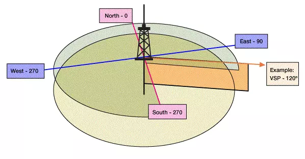
Vertical Section Azimuth – The proposed azimuth of the vertical section plane or proposed direction of the well.
Vertical Section Plane – An imaginary 2-dimensional plane having vertical (Z) and horizontal (X) dimensions. It is more easily pictured as a cross-sectional plane that originates along a vertical line extending straight down from the well’s surface location, and which proceeds horizontally away from the location along the azimuth bearing that the well is supposed to follow. It is usually abbreviated VSP and defined as a direction 0 -360 degrees (azimuth) or “North xx.x degrees East”, “South xx.x degrees West”, etc. The vertical dimension is not specified (Figure 7).