Related Articles


Controlling Trajectory of Directional Wells
This section describes the tools and techniques used to control the path of a wellbore. Starting with the oldest method, we show how the process has evolved to provide better steering control and smoother wellbores.
Rotary and Sliding Modes
In nearly all cases (with the exception of wells drilled from slant-hole rigs), wells must first spud vertically before building wellbore angle. Controlled deviation from vertical begins at a pre-determined depth called the Kick-Off Point, or KOP (Figure 1: KOP -where the directional drilling starts).
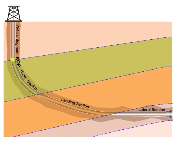
The vertical segment of the well is drilled using conventional rotary methods, in which the drill string is rotated from the surface by a rotary table located beneath the derrick floor, or by a topdrive motor, suspended from the traveling block in the derrick. This type of drilling is called rotary drilling.
With conventional rotary assemblies, it is possible to make small changes in direction or inclination by changing either the weight-on-bit (WOB) or the rotary speed. Sharper directional changes can be achieved by adding or changing stabilizers. This approach was pioneered in the early days of directional drilling as a way of building long-radius curves.
For drilling short-to medium-radius curves, however, it is usually necessary to run a steerable mud motor. Upon reaching the KOP, therefore, the rotary BHA must be tripped out of the hole and replaced with a steerable mud motor.
Basically, the steerable motor allows two modes of drilling:
- Sliding mode: where circulating drilling mud provides power to the mud motor, which causes the bit to rotate while the drillstring does not rotate. The bit drills in the direction of the oriented toolface; thus building a continuous angle from the vertical.
- Rotary mode: where the entire drill string is rotated from the surface, negating the effect of the toolface bend, and thus causing the bit to drill a straight course.
In the overall directional drilling strategy, sliding is used for precision guidance of the assembly towards a prescribed target, whereas rotating involves no active guidance of the trajectory.
Steerable motors drive the bit in the direction set by the bent sub; the larger the angle of the bend, the sharper the “build” in the curvature of the wellbore. As with the rotary BHA, minor changes in direction are achieved by adjusting the weight on bit. Large changes in direction are made by lifting off bottom and reorienting the bent sub by rotating its position from the surface.
Once the proper trajectory is achieved, the lateral section of the wellbore is often drilled using a variation on the rotary mode. A conventional BHA may be used for straight, fast sections; or the steerable motor can be used like a conventional BHA, with the drill string rotated from the surface. The benefit of using a steerable motor in rotary mode is that any directional changes can be made without tripping for a new BHA. However, when a downhole motor is used to drill in rotating mode, the rate of penetration (ROP) is limited, to a degree, by how much weight on bit (WOB) the Directional Driller can safely apply. Though a certain amount of weight is needed, too much weight can stall or damage the motor, requiring an expensive trip for motor replacement. The Driller must balance the weight for increasing ROP against the operational limit of the motor.
In lateral sections, gravity works at 90 degrees to the horizontal drillstring, thereby producing considerable torque and drag on the drillstring. When a horizontal well is drilled forward in rotating mode, the rotation of the drillstring and mud motor can reduce torque and drag somewhat. However, during sliding mode the drillstring does not rotate, and this generally results in increased torque and drag. Another hindrance is stacking of drillpipe. (Stacking occurs as pipe is deformed in the curve of the build section, when pipe rests and drags against the formation.) These problems are overcome by increasing the WOB.
Though sliding mode provides greater control and flexibility over the directional aspects of drilling, it is gained at the expense of speed. Wells generally drill faster in rotary mode, and rotation of the drillstring has the added benefit of reducing the risk of getting stuck. Whenever possible, the Directional Driller will therefore opt to drill most sections of the hole in rotary mode, only using sliding mode for changing the hole angle.
Alternatives to Sliding
The practice of rotating until a course correction is needed, and then sliding to get back on track, can lead to increased wellbore tortuosity, along with a host of unwanted problems. Tortuosity is caused by doglegs and spiraling of the wellbore, both of which stem from rapid changes in azimuth and/or inclination. Tortuosity can ultimately shorten the lateral length of a horizontal well as problems mount, due to:
- Increased hole cleaning difficulty and an increased risk for stuck pipe.
- Increased bit bounce, and whirl (a deviation of bit rotation from the bit’s geometric center).
- Increased torque and drag.
- Increased vibration resulting in increased wear and tear on MWD/LWD tools.
- Increased difficulty in running casing and wear on tubulars.
After a well has been drilled, tortuosity can affect the completion program by restricting the ability to run completion tools, or increasing liquid holdup when the well is brought on-line.
Ideally then, the well should be drilled to plan, with as little sliding as possible to attain a smooth wellbore and minimal tortuosity. Alternatives to the old rotate-and-slide method have been developed which provide greater steering precision, smoother wellbores, better hole cleaning, and faster ROP. Two basic options have been developed to greatly decrease the need for sliding, and allow the drill string to continue rotating while changing course.
Adjustable Gauge Stabilizers
Directional Drillers found they could obtain the benefits of rotary drilling by using an adjustable stabilizer. Sometimes called 2D rotary stabilizers, the adjustable gauge stabilizer is used to control wellbore inclination, but does not have the capability to control azimuth. These stabilizers use adjustable buttons or blades to change the diameter of the stabilizer (Figure 2: Buttons mounted on stabilizer blades in closed and extended positions).

The stabilizers are either mechanically activated by adjusting weight on bit, or they are activated hydraulically by reducing, and then increasing mud flow from the pumps.
Adjustable stabilizers meet most horizontal drilling requirements to provide dependable, rapid, precise inclination control within tight target corridors. Because most trajectory corrections involve only inclination along a straight path (where azimuth is not a concern) these adjustable stabilizers can often be used to drill straight to TD. In wells that chase pay zones laterally from one target to another, the adjustable stabilizer is usually placed above a motor. This configuration eliminates sliding to correct for inclination, while allowing the motor to come into play when a change in azimuth is required.
Rotary Steering Systems
Rotary steering systems take directional control a step further, by controlling azimuth as well as inclination. These systems use a steering assembly mounted above the bit, and work by either applying a side force to the bit or by pointing the bit through a shaft or BHA deflection device. These systems are usually guided by directional sensors with feedback circuitry to orient the bit side force or maintain the prescribed trajectory (Figure 3: Rotary steering tool).

Early rotary steering models worked in much the same way as the adjustable stabilizer. These systems, sometimes classified as Push-the-Bit technology, steer the well by using adjustable pads or buttons that exert side forces on the wellbore to cause bit deflection. Second-generation systems are classified as Point-the-Bit technology. Instead of using external pads to push the bit sideways, these rotary steering systems steer the well by flexing a non-rotating drive shaft that is connected to the bit. This flexure changes the direction of the bit face. Most rotary steering systems can also provide automated steering capabilities by means of a pre-programmed trajectory, designed on the surface computer.
Overall Benefits
Though not always possible, rotary drilling has several advantages over sliding with a mud motor. Rotating allows more weight on bit and higher rates of penetration. Rotating generally does a better job of cleaning the hole of cuttings, thus reducing drag and the need for short trips to circulate up cuttings. The net result is an increase in footage drilled per day.
A smoother wellbore ultimately influences every parameter of the drilling and production process. First, the tool string is subjected to less downhole vibration, torque and drag. With a reduction in bit bounce and whirl comes improved bit performance and increased reliability of downhole motors and LWD tools. Finally, it smoothes the process of running casing and decreases holdup of produced fluids.