Related Articles


Core Acquisition Report
In the ideal scenario, the core analysis contractor would provide an experienced core acquisition technician (Figure 1) at the wellsite in the event of a continuous coring program through the reservoir in a key well for the company. The core analysis contractor would, therefore, be responsible for the careful boxing of the cores for their safe transit to their own laboratory (Figure 2).


When the contractor’s core technician catches the cores (Figure 3), their own laboratory and the oil company operating the well can be advised in the core technician’s interim report what drilling and coring procedures were followed (Austin, 2013) and if any special situations or problems were observed. Any of these special situations can be included in the final core analysis report. The core analysis laboratory’s technician should write a final report of their observations made at the wellsite, which will form part of the final core analysis report and allow the project’s geoscientists, petrophysicists and engineers to better appreciate the events that occurred at the wellsite.

Alternatively, an oil company employee or representative can fulfil this role and make a report such as the following example:
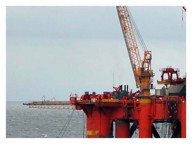
The following observations were made during the coring and subsequent core recovery at the wellsite of the drilling rig (Figure 4) Medco Dolphin during the coring of well 11/29-1, onshore Nigeria on 2 December 2014.
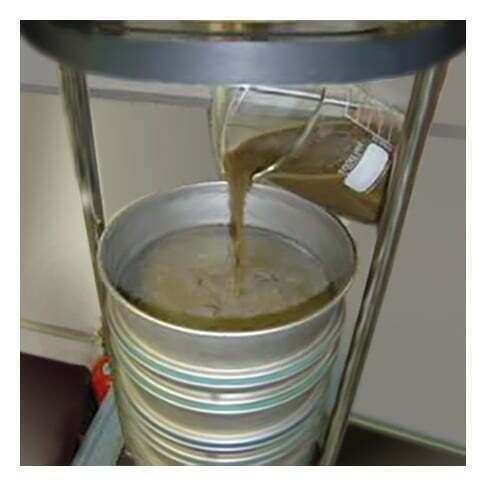
A slight drilling break occurred a sudden increase in the rate of penetration during the drilling of the well uphole of Core Number 1. When this increase in the penetration rate is significant, it can indicate a formation change, such as the bit drilling a sandstone interval faster than it was drilling the shale section immediately above. This sandstone interval, 21 ft thick, was not cored; the first core in the well was cut, starting at 8,559 ft after a much more pronounced second drilling break of 14 feet, during which the rate of penetration tripled with the same drilling parameters applied. After only 4 ft of coring, the Christensen wellsite coring contractor felt that the core barrel had jammed off, but the wellsite geologist’s decision was to temporarily continue coring. A total of 29 ft was cut prior to the core barrel being pulled to the surface. The low core recovery may have been caused by the core barrel being jammed off after only 3.5 ft, probably caused by the hard shale interval at 8,562 ft. This can be a common occurrence if the underlying sediments are poorly consolidated, pushing the harder shale sequence into the core barrel. While recovering the 3.5 ft of core from the core barrel, it was observed that the coring mud within the core barrel was a thick slurry and may therefore have contained some unconsolidated material. A sieve analysis (Figure 5) of this sand is included within the final core analysis report. The recovered 3.5 ft. of core was removed by hammering the inner core barrel.
This core report helps to locate the origin of the 3.5 ft of core recovered. A theory, with some supporting evidence, is offered to explain the low level of core recovery, which may be useful in future wells in this field and in the general area. Without such a useful core acquisition report, it is unlikely that this potentially important information would have been retained within the oil company’s documentation for future reference.
Field Procedures Coring Report
A good practice is also to document the additional field procedures (Badillo, 2013) for cores, an example of which is this report of the Field Procedures for Well 90/2-1, Onshore Indonesia: Core No.2:
Plastic sleeve coring equipment, in conjunction with water base drilling fluids, was used to extract the shallow core samples from well 90/2-1 September, 2014. These cores were handled by the Core Service Company field personnel.
Core Handling and Marking
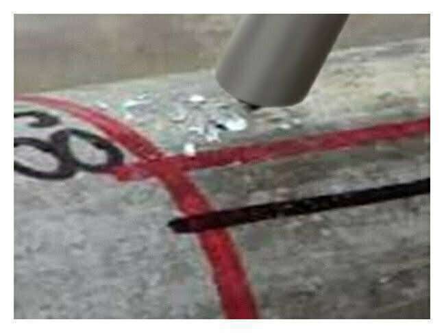
Prior to coring, the PVC core barrel liners were marked for orientation with parallel scribe lines, a red line on the right and a black line on the left (Figure 6), looking towards the top of the liner (Blackbourn, 2009). After each core was cut, the inner core barrel was laid on the rig’s catwalk and the PVC sleeve containing the core was extruded from the barrel and cut into a number of three foot sections (Figure 7). Each such section was measured and marked for depth at one-foot intervals. Where applicable, depths were assigned such that any core not recovered was attributed to the bottom of the cored interval. The core sections were boxed and then placed in a refrigerated truck maintained at a temperature of 35º F / 1º C at the wellsite. Upon completion of the coring, the cores were transported to the Jakarta, Indonesia laboratory, where they were scanned for spectral gamma activity and placed into chilled storage.