Related Articles


The Roberts #3 Well
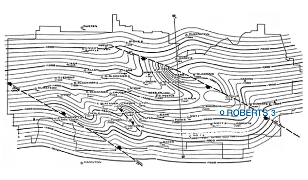
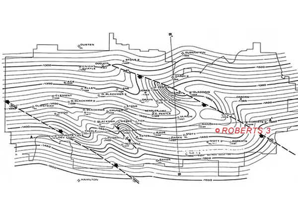
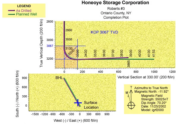
Preliminary studies indicated that a horizontal well would increase field injection/withdrawal capacity by about three times the deliverability of a vertical well drilled in the same location. It was determined that the eastern side of the field, with relatively tight permeability and widely spaced wells, would benefit most from the placement of a horizontal wellbore while providing the fewest obstacles to horizontal drilling. An existing vertical well was selected for re-entry to avoid a prolonged regulatory process and obviate the need for archeological and environmental assessments normally required for permitting new wells. The Roberts #3 well, with good structural position and casing set above the storage interval, was deemed to be the optimal candidate for sidetracking and geosteering (Figure 6: Roberts #3 well location).
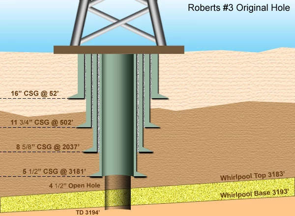
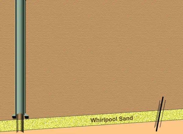
The Roberts #3 (Original Hole) was drilled vertically in 1956 to a Total Depth of 3194 feet, and had 5 1/2-inch production casing set at 3177 feet. This well produced gas from the Whirlpool formation, which was encountered between 3183 -3193 feet. After the field was acquired by HSC, the Roberts #3 was converted to a storage well. (Figure 7: Schematic cross-section of Roberts #3 well).
Structural Influences on Wellbore Design
Once the candidate well was chosen, the next step was to determine the best direction in which to drill the lateral extension. Wellbore azimuth was influenced by three key structural parameters: (Figure 8: Structural factors).
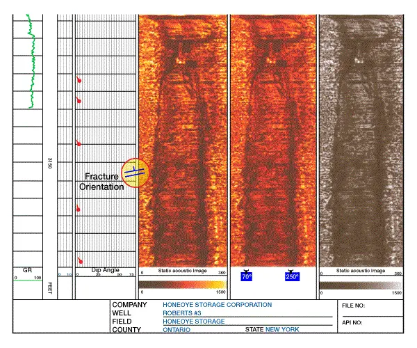
- Fractures: To obtain optimal production, the lateral wellbore needed to be placed at right angles to the natural fracture system. A Circumferential Borehole Imaging Log (CBIL) was therefore run in the Roberts #3 to determine the orientation of fractures within the Whirlpool Sandstone. This log revealed a fracture trending NNE-SSW, normal to the principal stress field.
- Faulting: Two faults, trending NNW-SSE, lie to the east and west of the Roberts #3 well.
- Water Contact: The field’s original gas-water contact south of the well.
These factors led the Geosteering Team to select the optimal azimuth for the sidetrack well. A wellbore drilled perpendicular to the predominant fracture trend would increase the likelihood of intercepting the greatest number of fractures, greatly increasing permeability and enhancing deliverability of the wellbore. The CBIL interpretation indicated the well should be sidetracked either to the NNW or the SSE. This direction parallels two faults near the well, and thus reduces the chance of crossing one of the faults. However, by turning NNW, the wellbore would drill updip, away from the gas-water contact to the south. With this in mind, the Geosteering Team selected a kickoff azimuth of 330º (N30W).
Well Plan -Roberts #3 Sidetrack
Given the wellbore azimuth, target depth, and dip, the overall design for this short/medium-radius well became a matter of simple geometry. Basically, the plan called for two bridge plugs to be set in the Roberts #3 (Original Hole): one plug at the top of the reservoir storage zone, and the other plug at the kick-off point. (Figure 9: Animated drilling plan). After orienting and setting a whipstock, a 4 3/4 inch mill would be used to open a window in the 5 1/2 inch casing. This provided the opening to drill a 4 3/4 inch oriented hole from KOP to approximately 3242’ MD / 3188’ TVD, building angle at a rate of 0.6º per foot, over a radius of 150-feet. After landing in the target zone, an oriented hole would be drilled within the payzone for approximately 1000 feet (from 3243’ to 4243’ MD).
The Geosteering Plan
Several parameters had to be defined in order to ensure that the wellbore stayed on track and on target.
- Kick Off Point: As a sidetrack to the vertically drilled Roberts #3 well, the depth of the pay zone in the proposed sidetrack was precisely determined by well logs from the vertical hole. Structure maps on this field revealed a gentle dip rate of 0.62º, (or a change in elevation of 1.08 feet per 100 feet horizontally). With other nearby wells providing tight structural control, no drastic change in dip or structure was detected between the vertical well and the target section of the horizontal well, which was projected to land just 150 feet from the original well. Therefore, rather than picking a stratigraphic marker, the KOP was determined on the basis of geometry from the target back to the original hole, where the whipstock would be set.
- Reservoir Thickness: Isopach mapping of the target zone revealed that the thickness of the target zone in this part of the field was projected to range from 8-10 feet.
- Lateral Stratigraphic Variation: Regionally, the Whirlpool Sandstone is known as a sheet sand that displays a well-defined “clean” gamma ray log response which gradually fines upward as clay content increases. Correlations between logs from neighboring wells revealed no significant lateral variation in stratigraphy.
- Identification of the Last Chance Marker: The Power Glen Shale is a distinctive member of the Medina Group that overlies the Whirlpool Sandstone, and was selected as the Last Chance Marker.
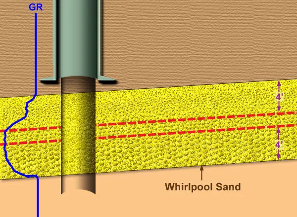
- Stratigraphic Center-Line with Tolerances: It was recognizedt hat drilling at, or just below the center-line of this thin sandstone unit would probably expose the cleanest part of the zone. However, because this zone was so thin, any minor deflection would increase the risk of throwing the bit out of the Whirlpool; therefore, a line that was 4 feet below the top of the of the formation, and 4 feet above its base was defined as the sweet-spot for this well. (Figure 10: Cross-section of target zone with well log showing fining upward sequence in Whirlpool.)
Depth to Target at 0 Vertical Section: The target depth immediately beneath the rig location was 3241′MD/3186′TVD @ VS = 0 . (Expected landing depth at 150′ VS = 3243′MD/3188′TVD .) (Figure 11: Projected drilling trajectory).
- Average Dip / Dip Variation: Average dip across the field was determined to be 0.6º to the South, ranging from 0.5º to 2º. Dip measurements from the Roberts #3 Original Hole CBIL log showed dips ranging from 1.3º to 2.0º (Figure 12: CBIL Log). (Note that dip “tadpoles” on the Dip Angle log point in a northwesterly direction. This direction is in contradiction to the overall southerly field dip. However, tadpole orientation must be discounted from this display, because this CBIL tool was run without an orientation module to measure borehole deviation, and the borehole was logged on the assumption that deviation was zero. Even a slight borehole deviation would therefore affect the overall tadpole orientation)
- Structural Model: Only one target was selected for this well, so no elaborate modeling was required. Despite this fact, structure maps were created for the top of the pay sand, along with the top of the Irondequoit Limestone, the top of the lowermost sand that can be correlated directly overlying the pay zone. These maps revealed no disconcerting changes in the structural trend from one horizon to the next. However, the structural model revealed the presence of two normal faults near the Roberts #3 well. These NW-SE trending faults bracketed the well, with one fault located to the NE and one located to the SW of the Roberts #3 well. These faults played a role in determining the azimuth of the horizontal wellbore.
- Depth to Gas / Oil / Water contacts: The original gas/water contact, which defines the southern boundary of the field, was found at a depth of -1491 feet subsea, and lies approximately 3000 feet to the south of the Roberts #3 Original Hole. This contact influenced the decision to point the well in a Northwesterly direction (away from the contact).
- Lateral exposure to target: Friction losses during flow increase along the lateral section of a wellbore with each foot drilled horizontally. Beyond a certain horizontal length, friction loss will eventually increase to a point where additional lateral extension will contribute only marginally to the well’s performance. This is especially true in gas wells, because high velocities in the near-wellbore region create additional pressure drop due to inertial effects.
- Build Up Rate for Curve: The well was planned as a short-to medium-radius well, kicking off from a previously-drilled Roberts #3 (Original Hole), which provided tight structural and stratigraphic control over the target zone of the horizontal well. The BUR of 0.6º per foot was planned so that the well would intercept the target at about 150 feet from the original hole. A minimal dip was anticipated, requiring a gentle rise of 11 feet to keep wellbore on the centerline.