Diagnostic Evidence
Seismic
Due to relative lithologic homogeneity, braided stream deposits do not often show internal reflections. Shales are too thin and localized to generate any significant responses. Figure 1 (Possible braided stream/alluvial fan deposit in seismic section) is a probable example of the overall lense-like geometry and “poor” internal seismic character of such a deposit.

At the same time, if the facies is thick enough – that is, if it represents sedimentation for much or all of a geologic period, certain large-scale depositional changes will most likely have taken place, and thus the interfaces these have created will generate continuous reflections. This is shown by a seismic section of Prudhoe Bay field, where an apparent braided river facies composes the entire Permo-Triassic section. (Figure 2, North-south seismic section through the discovery well at Prudhoe Bay. Note the detail of interpretation possible on this section. Updip truncation of the Permo-Triassic section against the unconformity is clearly seen.)

Wireline Logs
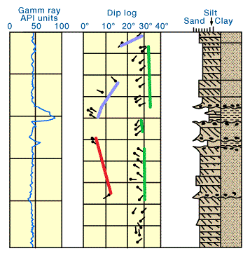
Figure 3 (Log of a braided alluvial sequence showing characteristic monotonous log response.

Note that the gamma log is neither as clean as that for eolian deposits, nor as shaley as meander channel flood plain alluvial sequences. Azimuth frequency plots reflect the linear trend of this type of river.) displays the somewhat idealized log response of a braided stream deposit. Some crude fining-upward portions of the curve can be discerned, but grain-size variation is most often too small to produce a convincing bell-shaped channel pattern. Instead, the gamma ray curve normally remains monotonously at lower values, with occasional spikes. This can usually be interpreted as a section composed mainly of coarse sediment, encasing a few thin, finer-grained interbeds. Though the mostly “massive” profile is not singular to braided stream deposits, it does indicate an overall sedimentary character that should clue in the exploration geologist to this possibility.
In terms of its dipmeter signature, this facies mainly shows the multiple stacking of channels. Within each channel, azimuths and dip amounts are clustered into separable groupings. Channel switching is, of course, characteristic, but azimuth changes will usually remain within a 90° arc, since individual channels are not highly sinuous and will not wander far from the overall downstream direction. Consequently, this direction — and the probable long dimension of the sand body as a whole — can often be found by bisecting the arc when it is plotted on an azimuth frequency diagram. If little tectonic disturbance has occurred, dip amounts will vary from near zero in planar beds to above 40° in the case of convoluted bedding. Most crossbed sets will range from 5° to 25°, with tabular types representing the higher end of this range.
Cores
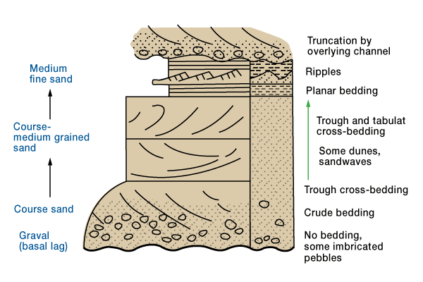
Core samples taken from a braided alluvial section can reveal either a homogeneous section of coarse, crossbedded and gravelly sandstones, or a diverse range of grain sizes and sedimentary structures. Again, well-preserved individual sequences begin with a sharp erosional base that marks the channel floor and is overlain by an upwardly-fining progression of grain sizes and sedimentary structures. Figure 4 (Idealized “outcrop” showing succession of grain sizes and sedimentary structures in a single channel sequence of a braided alluvial system) shows the general relationships between grain size and sedimentary structure.

 Petro Shine The Place for Oil and Gas Professionals.


