The Material Balance Equation
Expansion, Production, and Influx Terms
The material balance equation is an expression of the conservation of the mass of oil, gas, and water in the reservoir. The application of the conservation principle to the gas phase, for example, requires that the mass of gas in the reservoir at any time be equal to the mass of gas initially in place minus the mass of gas that has been produced. The mass of gas is calculated by
mass of gas=(volume of gas at standard conditions)×(density of gas at standard conditions)
The statement of the conservation of the mass of gas may be written as
![]()
or
![]() ………… (1)
………… (1)
where Gt, G, and Gp are, respectively, the gas in the reservoir at any time, the initial gas, and the produced gas (all in standard volumes). ρgs is the density of gas at standard conditions.
Because of the form of Equation 1, some authors refer to the MBE as a volumetric balance. This is misleading, since Equation 1 was derived from a mass balance equation. The complete derivation of the MBE requires expressing the three terms Gt, G, and Gp in Pertinent parameters. The resulting equation is
![Rendered by QuickLaTeX.com N_{p}[B_{o}+(R_{p}-R_{si})B_{g}]+B_{w}W_{p}=N(B_{o}-B_{oi})+\dfrac{NmB_{oi}}{B_{gi}}(B_{g}-B_{gi})+\dfrac{NB_{oi}}{1-S_{wi}} \ (c_{r}+ S_{wi}c_{w})\Delta p+W_{e}](https://petroshine.com/wp-content/ql-cache/quicklatex.com-8355b11ab0c9b5547f1fc3658b4ba775_l3.png)
Note: only the expansion of rock and its associated water in oil zone is considered in Equation 2.
where:
Np= cumulative oil production, STB
Bo= two-phase formation-volume factor, ![]()
Rp= cumulative produced GOR, ![]()
Rsi= initial gas in solution, ![]()
Bg= gas formation-volume factor, ![]()
Bw= water formation-volume factor, ![]()
Wp= total water produced in STB
N= initial oil in place, STB
Boi= initial two-phase formation-volume factor
m= ratio of gas cap pore volume to oil leg pore volume
Bgi= initial gas formation-volume factor
Swi= initial water saturation, fraction of pore volume
Sw= water saturation, fraction of pore volume
cr= rock compressibility, ![]()
cw= water compressibility, ![]()
![]()
![]() = initial reservoir pressure, psi
= initial reservoir pressure, psi![]() average reservoir pressure at the time of interest t, psi
average reservoir pressure at the time of interest t, psi![]() = cumulative water influx, RB
= cumulative water influx, RB
The two terms on the left-hand side indicate the total fluids production in reservoir volumes. The first three terms on the right-hand side are, respectively, the total expansion of the hydrocarbon in oil zone, the total expansion of the gas in gas cap, and the total expansion of the rock and its associated water. The last term is the water influx. Thus, a statement of the MBE which is simple and easy to remember is: total fluids produced in reservoir volumes equals total expansion of the hydrocarbon in the oil zone, the gas in the gas cap, and the rock and its associated water, plus the water influx in oil zone.
Compressibility of Rock and Water Terms
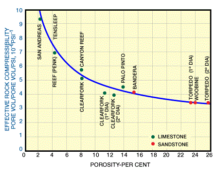
Normally one thinks of the water and rock as being incompressible. In fact, they are compressible. The rock compressibility is a function of its porosity and consolidation (Figure 1).

It can be as low as 3⋅10−6 ![]() and higher than 20⋅10−6 (Coats 1980). The water compressibility does not vary widely like the rock compressibility. It normally ranges between 3 and 6⋅10−6
and higher than 20⋅10−6 (Coats 1980). The water compressibility does not vary widely like the rock compressibility. It normally ranges between 3 and 6⋅10−6 ![]() .
.
To illustrate the meaning of compressibility and the unit vol/ vol/Psi consider two cubic feet of water that are under pressure. Assume the Pressure is decreased by 10 Psi and the water compressibility is 3⋅10−6 per psi. Since the pressure decreases by 10 psi, the two cubic feet of water expands by 2⋅10⋅(3⋅10−6)=6⋅10−5. The volume of water is now 2.00006 cubic feet.
Advantages and Limitations of the MBE
The primary advantage of the material balance equation is that it provides a valuable insight into the behavior of the reservoir and the contributions of the various drive mechanisms to the overall recovery. In the case of reservoirs with reasonable reservoir-wide fluid communication, the MBE provides a method of calculating the initial oil or gas in place, as well as the expected aquifer effects, by using actual production and pressure data. The MBE is the only method that employs the dynamic response of the reservoir to production as a means of estimating the volume of original fluid. What the MBE calculates is the fluid volume in the reservoir that is affected by production.
The dynamic response of the reservoir fluid to production is manifested in the pressure change. Thus, the initial fluid in place calculated by the MBE is indicative of the fluid volume in communication with the wells. In contrast, the volumetric method of estimating the fluid in Place is a static method. It does not differentiate between connected and isolated areas. For this reason, the fluid in place calculated by the MBE cannot be larger than that calculated volumetrically, assuming an accurate volumetric estimate.
The main disadvantage of the MBE is that it is based on a tank model (i.e., a zero-dimensional model). Therefore, it deals with average values of rock and fluid properties for the whole reservoir. As a result, it cannot be used to calculate fluid or pressure distributions, nor can it be used to identify new well locations or the effect of well locations and production rates on recovery. The MBE cannot be used to predict water or gas channeling, and cannot account for the effect of heterogeneities on the behavior of the reservoir. When any of these factors is significant, reservoir simulation is required to predict precisely the behavior of the reservoir.
A. Derivation of the Material Balance Equation
We will derive the MBE based on the gas in the oil zone. The gas in scf in the oil zone at time, t, is given by Equation A1.
![]() ………… (A1)
………… (A1)
where:
Gt= the total gas in the oil zone at time t in scf,
G= the original gas in the oil zone, scf, and
Gp= the total gas produced at time t, scf.
The gas in solution in scf=(N−Np)Rs
Gt has two components: the gas in solution in the oil and the free gas in the oil zone.
The free gas volume in the oil at time t, (scf) is equal to:
[the oil zone volume occupied by the initial oil – the volume of oil at time t – the decrease in the oil zone volume due to the expansion of the gas cap gas and the oil zone rock plus its associated water, and due to the net water influx]Note that all the terms between the brackets are in reservoir barrels.
The oil zone volume occupied by the initial oil = ![]()
The oil volume at time ![]()
Expansion of gas cap gas = ![]()
Expansion of oil zone rock = ![]()
Expansion of the associated water = ![]()
Net water influx = ![]()
Thus:
![Rendered by QuickLaTeX.com G_{t}=(N-N_{p})R_{s}+[NB_{oi}-(N-N_{p})B_{o}-\dfrac{NmB_{oi}}{B_{gi}}(B_{g}-B_{gi}) - \dfrac{NB_{oi}}{1-S_{wi}}(c_{r}+c_{w}S_{wi})(\Delta p)-(W_{e}-W_{p}B_{w})]\dfrac{1}{B_{g}}](https://petroshine.com/wp-content/ql-cache/quicklatex.com-88d06d500c626e09d6b15fd04e92159b_l3.png) ………… (A2)
………… (A2)
The original gas in the oil zone, ![]() ………… (A3)
………… (A3)
The total gas produced, ![]() ………… (A4)
………… (A4)
Substituting (A2), (A3), and (A4) in (A1) gives
![Rendered by QuickLaTeX.com (N-N_{p})R_{s}+[NB_{oi}-(N-N_{p})B_{o}-\dfrac{NmB_{oi}}{B_{gi}}(B_{g}-B_{gi})-\dfrac{NB_{oi}}{1-S_{wi}}(c_{r}+c_{w}S_{wi})(\Delta p)-(W_{e}-W_{p}B_{w})]\dfrac{1}{B_{g}}=NR_{si}-N_{p}R_{p}](https://petroshine.com/wp-content/ql-cache/quicklatex.com-bca8695c7beef2ccb5094c565f1d0086_l3.png) ………… (A5)
………… (A5)
Rearranging and collecting terms gives

Adding and subtracting ![]() to the left hand side term gives
to the left hand side term gives
![]() right hand side
right hand side
However, ![]() ; also at the bubble-point pressure Pi, [/latex]B_{o}=B_{oi}=B_{ti}[/latex], since
; also at the bubble-point pressure Pi, [/latex]B_{o}=B_{oi}=B_{ti}[/latex], since ![]() . Substituting these relations in the previous equation gives
. Substituting these relations in the previous equation gives
![Rendered by QuickLaTeX.com N_{p}[B_{o}+(R_{p}-R_{si})B_{g}]+B_{w}W_{p}=N(B_{o}-B_{oi})+\dfrac{NmB_{oi}}{B_{gi}}(B_{g}-B_{gi})+\dfrac{NB_{oi}}{1-S_{wi}} \ (c_{r}+ S_{wi}c_{w})\Delta p+W_{e}](https://petroshine.com/wp-content/ql-cache/quicklatex.com-8355b11ab0c9b5547f1fc3658b4ba775_l3.png) ………… (A6)
………… (A6)
 Petro Shine The Place for Oil and Gas Professionals.


