ad
GeologyPetrophysics
Trending

Shale Content | Shale Content and Petrophysical Evaluation

Structural Shale Model


Structural shales are a particular type of shale distribution in which the shale exists as grains within a rock framework, in contrast to the situations for dispersed shale and laminar shale.

Structural Shales

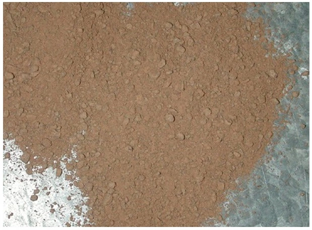
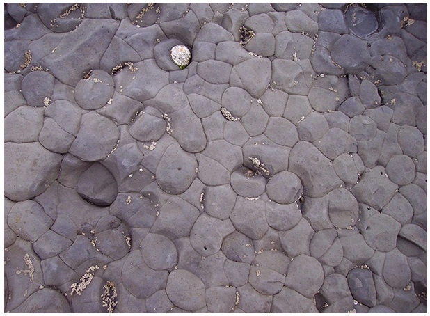
In the structural shale model (Figure 1), clay grains (Figure 2), often aggregates of clay particles (Figure 3) or mudstone (Figure 4) clasts, take the place of sand grains (Figure 5).

Structural shale model with the incremental replacement of sand grains by clay grains, shale content, Shale composition, Petrophysical analysis, Shale reservoir characterization, Porosity evaluation, Shale mineralogy, Petrophysical properties, Organic matter content, Shale gas potential, Petrophysical modeling, Clay content analysis, Shale permeability, Petrophysical interpretation, Shale formation evaluation, Total organic carbon (TOC), Shale geomechanics, Petrophysical parameters, Brittle shale, Shale facies analysis, Petrophysical logs, Shale porosity types, Petrophysical measurements, Shale core analysis, Effective porosity, Shale pore structure, Petrophysical evaluation methods, Shale water saturation
Figure 1: Structural shale model with the incremental replacement of sand grains by clay grains
Clay grains, shale content, Shale composition, Petrophysical analysis, Shale reservoir characterization, Porosity evaluation, Shale mineralogy, Petrophysical properties, Organic matter content, Shale gas potential, Petrophysical modeling, Clay content analysis, Shale permeability, Petrophysical interpretation, Shale formation evaluation, Total organic carbon (TOC), Shale geomechanics, Petrophysical parameters, Brittle shale, Shale facies analysis, Petrophysical logs, Shale porosity types, Petrophysical measurements, Shale core analysis, Effective porosity, Shale pore structure, Petrophysical evaluation methods, Shale water saturation
Figure 2: Clay grains
Size and shape comparison of typical clay and sand particles, shale content, Shale composition, Petrophysical analysis, Shale reservoir characterization, Porosity evaluation, Shale mineralogy, Petrophysical properties, Organic matter content, Shale gas potential, Petrophysical modeling, Clay content analysis, Shale permeability, Petrophysical interpretation, Shale formation evaluation, Total organic carbon (TOC), Shale geomechanics, Petrophysical parameters, Brittle shale, Shale facies analysis, Petrophysical logs, Shale porosity types, Petrophysical measurements, Shale core analysis, Effective porosity, Shale pore structure, Petrophysical evaluation methods, Shale water saturation
Figure 3: Size and shape comparison of typical clay and sand particles
Clay minerals forming a mudstone, shale content, Shale composition, Petrophysical analysis, Shale reservoir characterization, Porosity evaluation, Shale mineralogy, Petrophysical properties, Organic matter content, Shale gas potential, Petrophysical modeling, Clay content analysis, Shale permeability, Petrophysical interpretation, Shale formation evaluation, Total organic carbon (TOC), Shale geomechanics, Petrophysical parameters, Brittle shale, Shale facies analysis, Petrophysical logs, Shale porosity types, Petrophysical measurements, Shale core analysis, Effective porosity, Shale pore structure, Petrophysical evaluation methods, Shale water saturation
Figure 4: Mudstone
Sand grains, shale content, Shale composition, Petrophysical analysis, Shale reservoir characterization, Porosity evaluation, Shale mineralogy, Petrophysical properties, Organic matter content, Shale gas potential, Petrophysical modeling, Clay content analysis, Shale permeability, Petrophysical interpretation, Shale formation evaluation, Total organic carbon (TOC), Shale geomechanics, Petrophysical parameters, Brittle shale, Shale facies analysis, Petrophysical logs, Shale porosity types, Petrophysical measurements, Shale core analysis, Effective porosity, Shale pore structure, Petrophysical evaluation methods, Shale water saturation
Figure 5: Sand grains

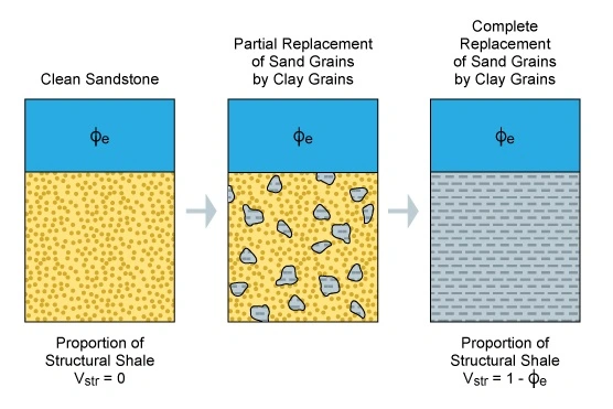
The effect on the porosity and permeability of the sandstone formation is often limited. However, the fact that the clay replacement grains normally have a different grain density and hydrogen index than the sand grains means that the presence of structural shale will have an effect on the LWD and wireline neutron porosity and density log responses. The maximum theoretical fraction of shale in the case where all the sand grains have been replaced by shale grains is:


(1- \phi _e)

The response of the neutron porosity and density tools can be written as:

\phi _{D} = \phi _{e} + (1 - \phi _{e})\cdot V_{str}\cdot \phi _{Dsh}

\phi _{N} = \phi _{e} + (1 - \phi _{e})\cdot V_{str}\cdot \phi _{Nsh}

Where:

ϕDsh= the apparent density porosity in the shale

ϕNsh= the apparent neutron porosity in the shale

Vstr= the volume of the structural shale/clay grains within the logged interval expressed as a decimal

ϕe= the true porosity in the clean sandstone

Which gives:

\phi _{e} = \dfrac{\phi _{D} \cdot \phi _{Nsh} - \phi _{N}\cdot \phi _{Dsh}}{\phi _{Nsh} - \phi _{Dsh}}

and

V_{str} =\dfrac{\phi _N - \phi _D}{\phi _{Nsh}\cdot (1 - \phi _D) - \phi _{Dsh}\cdot (1 - \phi _N)}

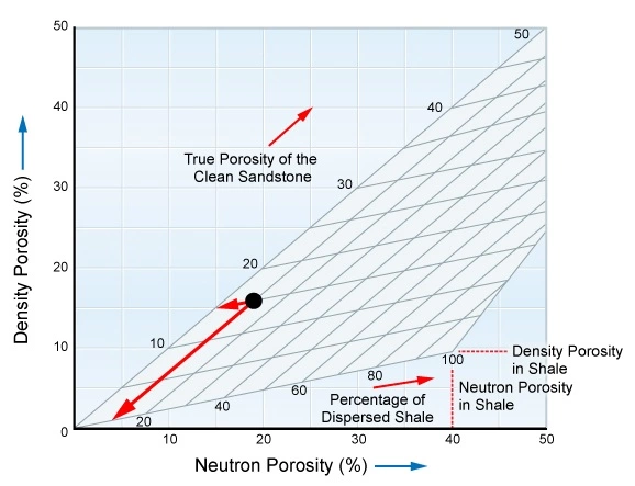
This is illustrated graphically in Figure 6 for the situation where:

  • Density porosity = 15%
  • Neutron porosity = 18%
  • Neutron porosity in shale = 40%
  • Density porosity in shale = 8%

In this case, the true porosity of the clean sandstone is determined to be 15% and the proportion of dispersed shale is determined to be 10%.

Density porosity versus neutron porosity crossplot for use with dispersed shale sandstone reservoirs, shale content, Shale composition, Petrophysical analysis, Shale reservoir characterization, Porosity evaluation, Shale mineralogy, Petrophysical properties, Organic matter content, Shale gas potential, Petrophysical modeling, Clay content analysis, Shale permeability, Petrophysical interpretation, Shale formation evaluation, Total organic carbon (TOC), Shale geomechanics, Petrophysical parameters, Brittle shale, Shale facies analysis, Petrophysical logs, Shale porosity types, Petrophysical measurements, Shale core analysis, Effective porosity, Shale pore structure, Petrophysical evaluation methods, Shale water saturation
Figure 6: Density and neutron porosity in a structural shale model

The electrical model for the structural shale model case assumes that, in addition to the Archie term, a shale conductivity term can be added so that:

C_t = \dfrac{\phi _e^m \cdot S_w^n}{a\cdot R_w} + \dfrac{V_{str}}{R_{sh}}

Thus:

S_w^n = \left( \dfrac{1}{R_t} - \dfrac{V_{str}}{R_{sh}} \right) \cdot \dfrac{a\cdot R_w}{\phi _e^m}

Total Shale Relationships

If the actual distribution of shale and clay in the formation is in doubt, an alternative interpretation approach is to use one of the so-called “total shale relationships” that are non-specific as to the type of shale model. Although only some of these relations are based on a sound experimental basis, one of the most widely used is this modified total shale relationship:

\dfrac{1}{R_t} = \dfrac{\phi _e^m \cdot S_w^n}{a\cdot R_w \cdot (1 - V_{sh})}+ \dfrac{V_{sh}\cdot S_w}{R_{sh}}


Previous page 1 2 3 4 5 6 7Next page

Related Articles

Leave a Reply

Your email address will not be published. Required fields are marked *

ad
Back to top button