Related Articles


Load Response: Flexural Compensation Model
Unlike the Airy compensation model, flexural models of compensation assume that the lithosphere has lateral strength. The hypothetical columns of Airy isostasy are mechanically coupled so that the lithosphere bends or flexes under loads (Figure 1 Flexural and local compensation occurs where layers within the lithosphere have sufficient lateral strength to support the load, as if the layers were connected by springs.
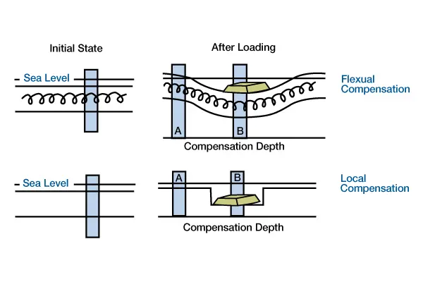
The load depresses the lithosphere beneath and adjacent to the load. In local compensation, layers within the lithosphere have no lateral strength [no springs] to support the load. The load depresses the lithosphere only at the position of the load). Flexural models are mechanical and mathematical analogs of a beam floating on a fluid of low viscosity. The elastic portion of the lithosphere (Figure 2, Four views of the layered structure of the earth, using different criteria for defining and recognizing layers.
Views 1 and 2 use kinematic/tectonic criteria, with layers corresponding to isotherms. View 3 defines layers according to composition and/or density. View 4 uses structural response to stress as a criterion for defining layers.) is analogous to a homogeneous mechanical beam or plate with a single value for mechanical strength or rigidity. Because there is lateral strength, a load will be distributed by the strength of surrounding columns and supported by buoyancy forces in the asthenosphere. The lateral strength of adjacent columns effectively pulls up on the lithosphere at the positions of loads, and pulls down on adjacent columns. Consequently, the lateral dimension of the deflection extends beyond the loaded column. Partial isostatic compensation due to lithospheric strength implies that vertical masses of columns are not equal, as we assume they are for Airy isostasy. Flexural models also commonly assume that compensation is achieved instantaneously after load emplacement, but this condition is not a requirement.
Both Airy and flexural response models are linear, implying that the lithospheric response to a supralithospheric load is equivalent to the response to a sublithospheric load of equal magnitude and dimension (Figure 3 [a], Linearity assumption of flexure, Supra- and sub-lithospheric loads of equivalent magnitude and dimension will cause downward deflections of equal magnitude.).
So, an upward force will cause an upward deflection equal in magnitude and dimension to the downward deflection caused by an equal, but downward, force (Figure 3 [b], Upward-directed load of equal magnitude and dimension will cause an upward deflection of equal magnitude). This result is important because it implies that we can analyze the responses to different types of loads without knowing the exact cause of loading; we only need to know the sizes, magnitudes and positions of loads to model their deflections. This also implies that we can linearly sum the responses to different kinds of loads. For example, if the lithosphere behaves elastically and its rigidity remains constant, then emplacement of a load will deflect the lithosphere downward, and subsequent removal of the load will deflect the lithosphere upward an equal amount. The final configuration would equal the initial configuration because the two deflections would sum to zero.
Turcotte and Schubert (1982) presented a derivation of a flexural equation based on a beam analog. Flexural models incorporate other mechanisms for supporting loads, such as lithospheric strength or intraplate stress, in addition to buoyancy forces in the asthenosphere. Because flexure is mechanically linear, we can mathematically add terms describing these mechanisms to modify the Airy response. Which terms we include depends on which load support mechanisms we consider most important. For some problems, the differences between using only Airy buoyancy forces as opposed to including lithospheric strength are small.
First, we rearrange Equation 1 so that its form directly equates loads with buoyancy forces:
 (1)
(1)
The load is now a function of horizontal position, x, emphasizing that loads can vary with position. Gravity, g, is added so that the units for the buoyancy term corresponds to force. Equation 2 is now in the form of Newton’s Second Law: the sum of the forces is equal to the mass times the acceleration, g. Keep in mind that this derivation assumes that mass is constant perpendicular to the x direction in the horizontal plane, so that all forces have units of force per unit length.
Second, we modify the Airy response by adding a term that describes the lateral strength of the lithosphere:
 (4)
(4)
In this expression, deflection, w, is now a function of position, x, because loads affect the lithosphere lateral to their positions. D, termed flexural rigidity, describes the lateral strength of the lithosphere and has metric units of Newton-meters or Dyne-centimeters. As D increases, the lithosphere becomes more rigid and distributes proportionately more of the load through lateral rather than vertical deflection (Figure 4, Deflections of lithosphere with different flexural rigidities, due to the same load.
The load is 40 km wide, 1000 m high, and has a density of 2.5 gm/cm3. Subsidence is filled with water and the initial topography is horizontal.). For an infinitely strong lithosphere, the Airy term would be zero; for an infinitely weak lithosphere, the flexural term would be zero. As shown in Equation 3, D is based on the lithospheric rock properties of Young’s modulus, E, and Poisson’s ratio,  , and the elastic thickness of the lithosphere, h (Figure 2):

If we define elastic thickness using an isotherm, then flexural rigidity depends on the thermal structure of the lithosphere. A hotter, thinner lithosphere is less rigid, or weaker, than a cooler, thicker lithosphere. Geodynamic models that invoke lithospheric cooling and contraction as a basin-forming mechanism also imply that lithospheric rigidity increases with lithospheric age.
Equation 2 also shows that the lithospheric response to a load depends on the magnitude of the load. Figure 5, (Deflections of lithosphere caused by loads with different magnitude.
Flexural rigidity is 1022 Nm, the initial topography is horizontal, and subsidence is filled with water. Each load has a width of 40 km and a density of 2.5 gm/cm3, but their heights are 250 m, 500 m, and 1000 m.), shows response curves to loads of differing magnitudes. As the magnitude of the load increases, the magnitude of deflection increases, but the shape of the deflection remains the same. Likewise, the lithosphere will respond differently to loads of equivalent magnitude, but different dimensions. The deflection due to a narrow load is larger beneath the load and narrower adjacent to the load than the deflection due to an equivalent but wider load.
Intraplate stresses may also partially support lithospheric loads (Cloetingh et al., 1985; Karner, 1986), and, like any other mechanism that might contribute to the lateral strength of the lithosphere, we can add a new term for this mechanism to Equation 2:
 (4)
(4)
N is the magnitude of the in-plane forces applied to the lithosphere by tectonic, intraplate stresses. Currently, most flexural models do not include intraplate stresses because they are not considered to be a dominant source of load support. However, this mechanism may influence the timing and magnitude of smaller changes in basin shape, thereby potentially influencing stratigraphic architecture.
There are many ways we can solve Equation 7 for deflection w, but a simple solution is to take advantage of linearity and solve the equation by summing the responses to individual columns of load (i.e., a line load solution, Figure 6, Line-load solution of the flexural equation.
The load is 50 km wide, 250 m high, and has a density of 2.5 gm/cm3. The flexural rigidity is 1022 Nm. The load if partitioned into five individual columns, each 10 km wide. The total deflection is the sum of calculated deflections caused by each load column. The half width of a basin is the distance between the center of the load and the position of no deflection. The flexural parameter, λ, is a measure of the half width of a basin.). (For a more complete discussion of this solution method, see Jordan (1981) or Turcotte and Schubert (1982)). Using this approximation, we can rearrange the terms and get:
![w = \dfrac{Load}{\rho_m - \rho_r}\, \cdot e^{-\lambda\,x}\cdot \left[ \cos(\lambda \, x) + \sin(\lambda \, x) \right]](https://petroshine.com/wp-content/ql-cache/quicklatex.com-e4467cccf1694519024bbf4effb7961a_l3.png "Rendered by QuickLaTeX.com") (5)
(5)
The amplitude of this expression is simply the Airy isostasy term. This term is modified by exponential and sinusoidal spatial factors lateral to the load. In this expression, the flexural parameter, l, determines the width of the deflection profile (Figure 6). As l increases, the deflection decreases more rapidly away from the position of the load. The exponential term controls how quickly deflection decreases away from the load, and the sinusoidal terms control the curvature of deflection.
The flexural parameter depends on flexural rigidity and the deflection replacement mass:
 (6)
(6)
As the replacement mass density, ρr, increases, l will decrease, and the half-width of the basin will increase. For a given mass, a basin filled with sediment will be broader than if it had been filled with water or air (Figure 7, Deflections cause by variations in the replacement mass.
For each calculation, the load magnitude and dimension were equivalent, but the replacement masses were different. The load is 90 km wide, 200 m high, and has a density of 2.5 gm/cm3. Flexural rigidity is 1022 Nm. Subsidence is filled with air [no density], water [1.0 gm/cm3], and sediment [2.5 gm/cm3]. With an increasing replacement mass density, the basin becomes wider and deeper.). As flexural rigidity, D, increases, l decreases, and basins will be wider for a given load (Figure 4).