Fluid Flow Equations in Reservoir Engineering
Darcy’s Law
Darcy’s law is an empirical relation that describes the fluid flow in porous media as a function of pressure gradient and the viscosity of the fluid. It is basically an extension of the principles of fluid dynamics to flow of fluids in porous media. It thus represents the equation of motion in reservoir engineering.
In 1856, Henry Darcy, a French civil engineer, published his experimental results on water flowing through sand-filter beds. The results showed that the rate of flow through the sand bed was proportional to the pressure head above the bed and to the cross- sectional area of the filter, and inversely proportional to the viscosity of the water and the thickness of the bed. Later, other investigators extended Darcy’s law to fluids other than water, and the constant in Darcy’s equation was written as a ratio of permeability to viscosity.
These relations are expressed mathematically in the following equation:
![]() ………… (8)
………… (8)
where:
q = flow rate in ![]()
k = permeability in direction of flow, darcies
μ = viscosity in centipoise
A cross-sectional area in cm2
![]() = pressure gradient in atm/cm
= pressure gradient in atm/cm
Note that the negative sign in front of the equation is needed to obtain a positive q, since dp/dx is negative. The most common application of Darcy’s law is to linear and radial flow geometries.
Linear Flow
In linear flow, A is constant (Figure 1).
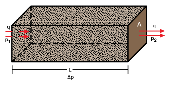
Re arranging Equation 8 gives
![]()
Integrating between X = 0 and X = L gives
![]()
or
![]()
In engineering units, the above equation becomes
![]() ………… (9)
………… (9)
where:
q = flow rate in reservoir bbl/day
A = area in ft2
k = permeability in direction of flow, (md)
p1 pressure at the inlet end, psi
p2 pressure at the outlet end, psi
μ = viscosity in centipoise (cp)
L = length, ft
Radial Flow
In radial flow, which represents the flow pattern around a well, ![]() (Figure 2). Substituting in Equation 8,
(Figure 2). Substituting in Equation 8,
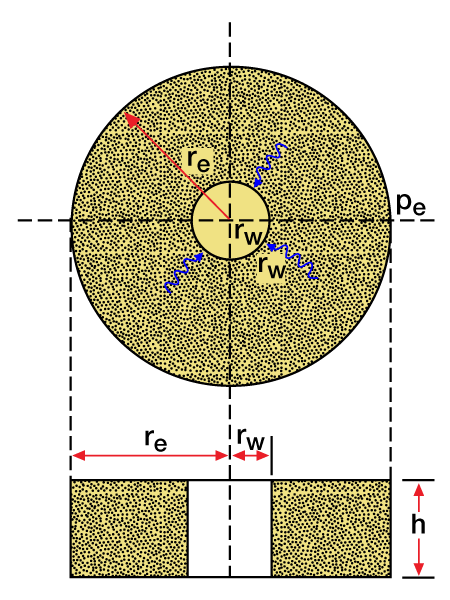
rearranging and integrating gives
![]()
This yields

and in engineering units
 ………… (10)
where:
h= thickness of bed, ft
pe pressure at outer boundary, r = re
pw pressure at the inner boundary, r = rw
re radius of the outer boundary, ft
rw radius of the inner boundary, ft and the rest of the symbols are as defined previously.
In the case of a well, rw and re represent, respectively, the wellbore radius and the radius of its drainage area.
The assumptions underlying Darcy’s law require that the flowing fluid be incompressible, and that the flow be laminar. Strictly speaking, while reservoir fluids are compressible, Darcy’s law is still a very good approximation of the flow of oil and water. In the case of gas, it is used if the gas production is associated with the oil, and a modified form of it is used for gas wells. The modified form is
 ………… (11)
where:
q= flow rate in MSCF/D at standard conditions of temperature and pressure
k= permeability in direction of flow, millidarcies
z= gas deviation factor (evaluated at average pressure)
μ= viscosity in centipoise (cp) (evaluated at average pressure)
TR= reservoir temperature, ∘R=460+∘F
h= thickness of bed in ft
Relative Permeabilities
All of these equations assume that only one fluid saturates the porous media; thus k is the absolute permeability. However, as mentioned previously, water is always present. Furthermore, in oil reservoirs, oil, gas, and water exist together, below the bubble-point. In such cases, one must use the effective permeability to the phase of interest in place of the specific permeability. Normally, one replaces the effective permeability by
![]()
where:
kr = the relative permeability
Effect of Saturation on Fluid Flow
Relative permeability is a function of saturation. The relative permeability behavior for an oil-water system is illustrated in Figure 3.
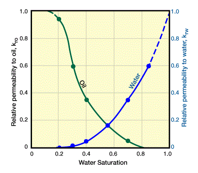
Note that the figure shows that relative permeability values equal to zero exist for saturation values greater than zero. This means that a critical saturation value must occur before relative permeability exceeds zero, that is to say, before the fluid starts to flow.
Gas-Oil Ratio (GOR) Equation
Gas production associated with the oil may come from two sources. These are:
- the flow of the free gas in the oil zone, which occurs when the pressure in the oil zone is below the bubble-point and the gas saturation is above its critical value;
- the gas that is liberated from the oil during its trip to surface because of the drop from reservoir pressure to surface pressure. This portion of gas is expressed in standard cubic feet/stock tank bbl (SCF/STB) or cubic meters per cubic meter (m3/m3), and is indicated by Rs.
The ratio of the flow of free gas to the flow of oil at standard condition is calculated by means of Darcy’s law and is given by
![]()
The ratio of the rate of gas to oil production, GOR, is
![]() ………… (12)
………… (12)
where:
GOR= gas-oil ratio, SCF/STB
krg= relative permeability to gas, fraction
B0= oil formation volume factor, RB/STB
kro= relative permeability of oil, fraction
Bg= gas formation volume factor, RB/scf
Rs= the gas in solution, SCF/STB.
Fractional Flow Equation
When there is a natural influx of water from an aquifer, or when water is injected into an oil reservoir, a simultaneous flow of oil and water occurs. The oil and water fractions in the flowing stream may be calculated by means of Darcy’s law. The oil and water fractions, fo and fw, are defined by
![]() , and
, and
![]() ………… (13)
………… (13)
but, in linear systems,
![]() and
and
![]()
substituting in (13) and simplifying gives
 ………… (14)
and
 ………… (15)
 Petro Shine The Place for Oil and Gas Professionals.
