Related Articles

Sandstone Matrix Acidizing Treatments
Matrix acidizing in sandstone achieves the natural true permeability of the formation by removing clay damage. The stimulation fluids are pumped into the porosity (pore spaces) of the rock below fracturing pressure.
Since the acid is exposed to and reacts on such a large area of the formation, unreacted acid can be effective only for a short distance into the reservoir. Thus, this type of treatment is primarily designed to treat shallow damage in the immediate vicinity of the wellbore. Retarded hydrofluoric acid systems can penetrate farther. Of course, the effective penetration is also a function of the dissolving power and reaction rate, which depends on the properties of the acid and the mineral in the formation.
Reasons for Treatment
Sandstone formations usually have clays that swell or migrate, plugging pore spaces and decreasing permeability. Sandstone acidizing restores natural permeability and increases productivity by removing clay damage and controlling fines migration.
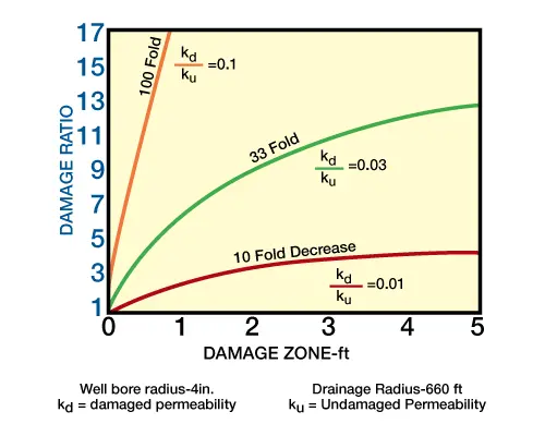
Figure 1 (effects of damage zone-permeability decrease) demonstrates damage ratio at various depths of damage for varying degrees of permeability decrease. Obviously, the greatest damage occurs near the wellbore.
Usually, acidizing an undamaged sandstone formation is not desirable. Theoretical production increases obtained from these treatments are rarely above 1.3 not enough to justify the acidizing cost. In some instances, however, a highly productive undamaged well can be stimulated enough by acidizing to show an economic advantage: a production increase results from pore enlargement in the zone adjacent to the wellbore. Figure 2 shows the effect on production of an improved permeability zone.

Treating Acids
Acids used in stimulating sandstone reservoirs generally contain some form of the highly reactive fluoride ion (F−). This ion is the only one that reacts significantly with sand and clay. Treating acids containing the fluoride ion include HCl–HF and HF-organic acid mixtures.
HCl–HF MixturesThis acid blend can be prepared by one of three methods: dilution of concentrated HF or, as is more frequently done, by mixing HCl with ammonium bifluoride (NH4HF2).
HF-Organic Acid Mixtures: Blends of HF-organic acids, are used occasionally to retard the reaction of acid on sand and clay, and to reduce corrosiveness. These can provide deeper penetration of unspent HF and, consequently, effective removal of deep damage. Either HF-formic or HF-acetic can be prepared from liquid HF, solid ammonium bifluoride (NH4F2), or ammonium fluoride (NH4F), and the corresponding organic acid.
All acid solutions should be prepared with fresh water. Sea water or brines should never be used in preparing acidizing fluid for HF-type treatments. Since these waters may contain sodium or potassium ions, they can cause formation-damaging precipitants.
HF reacts with SiO2 to give fluosilicic acid (H2SiF6) and water. This is one of the more important reactions of HF.
Rate of the reaction is primarily dependent on the following variables:
- type of mineral present
- size of sand grains
- temperature
- volume and/or strength of HF
- concentration of HCl contained in the blend
Decreasing sand-grain size increases surface area for a given weight of sand. The larger the surface area, the faster the acid reacts. The effect of temperature on the reaction rate is shown in Table 1 (below).
| Temperature | Reaction Rate Constant (cm/min) |
|---|---|
| 75° F | 3.89⋅10−5 |
| 100° F | 5.59⋅10−5 |
| 150° F | 11.27⋅10−5 |
| 200° F | 20.05⋅10−5 |
| 300° F | 51.46⋅10−5 |
This data show that increasing temperature significantly increases HF reaction rate on sand. Reaction rate is about 13 times faster at 300° F than at 75° F. The primary control on reaction rate, however, is the rate of acid movement and whether the acid contacts a fast or slow-reacting material. HF acid, for example, reacts relatively slowly with quartz, but much more quickly with feldspar or kaolinite. Increasing the acid volume and/or strength increases the distance unspent HF can be pumped into the formation.
Varying the concentration of HCl in the acid blends also affects the HF reaction rate on sand (Figure 3, influence of HCl on HF-sand reaction ). Increasing HCl concentration in HCl–HF mixtures increases the amount of sand that can be dissolved by equivalent concentrations of HF. Blends with greater HCl strengths react longer.

Fluosilicic and fluoaluminic acids, reaction products between HF on clay or sand, can react with sodium ions (NA+) or potassium ions (K+) to form precipitates.
The reaction of the sodium ion is:


The reaction products, sodium fluosilicate and fluoaluminate, are white, gelatinous solids which can partially plug permeability. These potentially damaging precipitants can be prevented by proper acid placement techniques. On the other hand, ammonium fluosilicate and ammonium fluoaluminate, reaction products with the ammonium ion, are completely soluble.
Reaction of HF on limestone (CaCO3) produces a very fine white precipitant: calcium fluoride (CaF2), along with water and carbon dioxide. Calcium fluoride can cause formation damage, but this problem is avoided by proper placement of HCl.
Treatment Technique (matrix acidizing)
The three key stages of fluid placement during an HF treatment are preflush, HF acid, and overflush or afterflush. Although various fluids may be pumped ahead of the preflush or behind the overflush, no change should be made in these three basic stages. This treatment technique is designed to be compatible with natural formation fluids. Figure 4 illustrates the basic HF acid treatment design.
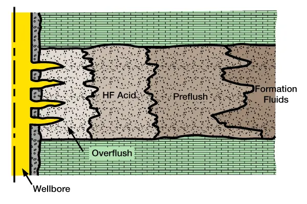
Preflush: A preflush fluid should always be pumped ahead of a fluoride-containing solution (e.g., HF acid). It forms a vital barrier between the acid and the formation fluids which prevents the formation of insoluble precipitants, such as sodium and potassium fluosilicates and fluoaluminates, and calcium fluoride (a reaction product of HF with limestone). If HCl is used as a preflush, it dissolves the limestone or dolomite, thereby reducing the possibility of the formation of insoluble precipitants. The preflush fluid must be compatible with both the formation fluid and the HF treatment.
A solution of 5 to 15% HCl or acetic acid is popular for displacing formation brines to prevent them from mixing with reacted HF. The solution is also useful in the removal of small amounts of calcareous cementing material. Both conditions can result in the development of insoluble precipitants.
Ammonium chloride (NH4Cl) is useful as a preflush if calcium chloride (CaCl2) has been used as a workover fluid. The calcium chloride should be either circulated out with a 3% NH4Cl solution or isolated behind a packer. Any calcium chloride left in the wellbore should be preflushed away into the formation with HCl or NH4Cl solution.
Diesel oil, kerosene, and certain crude oils may also be used as preflushes. However, their use is dependent on total compatibility with the formation fluids, the HF acid treatment, and all surfactants included in the treatment sequence.
HF Acid: After the preflush, HF acid is pumped into the formation. The treatment fluid should be of an adequate volume and have proper concentration. A 12% HCl-3% HF solution is the usual concentration for damage removal in a high-quartz, low-clay formation. A 13.5% HCl-1.5% HF solution may be used in a high-feldspar formation, and a 6.5% HCl-1.0% solution where high clay content is a factor. In extremely “tight” formations (i.e., those with less than 1 md permeability), a 3% to 7% HCl-0.5% HF solution may be used. Table 2 (below) provides more detailed acid-use guidelines for sandstone acidizing.
| Situation | Acid Type |
|---|---|
| HCl Solubility > 20% | HCl only |
| High Permeability (100 + md) | |
| High Quartz 80%, Low Clay <5% | 12% HCl – 3% HF1 |
| High Feldspar >20% | 13.5% HCl – 1.5% HF1 |
| High Clay >10% | 6.5% HCl – 1.0% HF2 |
| High Iron Chlorite Clay | 3% HCl – 0.5% HF2 |
| Low Permeability (20- md) | |
| Low Clay <5% | 6% HCl – 1.5% HF3 |
| High Chlorite | 3% HCl – 0.5% HF4 |
- Preflush with 15% HCl
- Preflush with Sequestered 5% HCl
- Preflush with 7.5% HCl or 10% Acetic
- Preflush with 5% Acetic
As mentioned earlier, when HF is pumped into a formation, a decrease in permeability occurs, with a possible corresponding increase in pump pressure. This condition is due to the initial rapid reaction of the clay, precipitation of hydrous silica, and the dislodging and migration of fines. The 3% and 6% HF concentrations demonstrate this initial reduction in permeability, followed by overall permeability increase. Occasionally, as demonstrated by the 9% HF concentration, the damage is complete, with the wellbore totally plugged (Figure 5, change in permeability observed during acidizing with various strength HF acid systems).
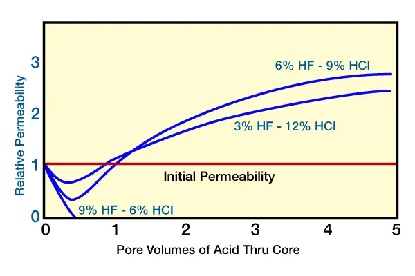
No more acid can be injected at this point without fracturing the rock. To maintain permeability, 3% HF is used for most treatments; in high clay content formations, even lower-strength HF should be used. Lower-strength HF acid concentrations generally present fewer problems than higher concentrations.
Overflush: The overflush, or afterflush, is designed to minimize the precipitation of Si(OH)4, which can limit the success of acid treatments. The overflush is also used to:
- displace unreacted HF into the formation, thus reducing corrosion, leaving more acid to react in the formation, and allowing for a shut-in period, should one be required (e.g., ahead of a gravel pack)
- displace HF reaction products away from the wellbore
- remove the oil-wet relative permeability problems caused by cationic surfactants, such as corrosion inhibitors
- stabilize clays and fines
- reestablish oil or gas saturation near the wellbore
Typical overflushes for HF treatments are 3% NH4Cl, 3% to 7% HCl, organic acid, diesel oil, kerosene, crude oil, and nitrogen (commingled with any of the above fluids, or by itself). Aqueous ofterflushes are the most effective in displaying spent acid from the near wellbore region.
The most common is 3% NH4Cl, because it is one of the few salts that will not precipitate insolubles with active or spent HF. Diesel is another frequently used overflush in oil-producing wells. Often, a mutual solvent is added to the overflush to improve saturation and relative permeability characteristics.
HF reacts very rapidly on clays. Consequently, a long shut-in time is not required. A slow return of the treatment load should begin as soon as practically possible. This minimizes fines movement; those that do move are more likely to come back to the wellbore without bridging. Allowing the reacted acid system to remain in the formation for extended periods of time increases the chance of fluid intermixing. Also, energy used to place all treating fluids may be dissipated.
Use of Additives (Matrix Acidizing)
During acid treatment of sandstone formations, fluids pumped into the rock pores contact a large surface area, where capillary pressures begin to govern flow rates and fluid recovery.
Thus, selecting the proper additives ensures that
- treated fluids are used throughout the acidizing sequence
- the additives are not adsorbed onto rock surfaces to leave virtually untreated acid solutions to penetrate the deeper portions of the formation
Figure 4 (HF acid treatment design), shows the preflush fluid in direct contact with formation fluids. To prevent emulsion problems and sludge deposits, the preflush fluids must be adequately treated to maintain compatibility with formation crude oil.
If the additives have a tendency to adsorb on the rock, steps must be taken to minimize their adsorption enough to allow adequate penetration. Surfactants can reduce the acid’s surface tension, and thus reduce capillary pressure and aid in cleaning up the reacted acid solutions.
Treatment Design (Matrix acidizing)
Before designing a sandstone treatment, the engineer should gather as much information as possible about the composition and properties of the formation. Although well data, cores, and formation materials are not usually available, the engineer needs to obtain or estimate information about the following:
- formation permeability
- fracturing pressure
- condition of the tubing
- wellbore geometry
Formation Permeability: Formation permeability must be estimated to calculate the injection rate possible during treatment stages. Generally, a minimum injection rate of 1/4 BPM should be achieved during final HF placement and overflush. Sometimes early injection rates may be very low, making it necessary to use the hesitation-squeeze technique of acid placement. However, if a proper analysis has been made of the wellbore condition by previous well testing or other estimates, the injection rate can be estimate before HF reaches the formation. Then, if the calculated treatment time is too long, a mini HF treatment can be run to open up more injectivity before the main acidizing volume.
Fracturing Pressure: Fracturing pressure must also be estimated to determine the allowable injection rate into a formation. Fracture gradients of new wells are usually available, but these values decline as the formation is depleted. A useful technique is available to estimate the effect of reservoir pressure decline on the fractured gradient.
Condition of the Tubing: Any rathole requires isolation or cleanout prior to acid placement. Tubing should be run to bottom, and the well circulated with a formation-compatible fluid to clean the wellbore of all debris and sludge. Otherwise, during the treatment the more dense acid will displace the rat-hole fluid and allow this debris and sludge to enter the perforations, potentially causing severe plugging.
Wells that periodically scale up can be treated for calcium scale by circulating acetic acid down the annulus and up the tubing. This action removes cumulative calcium carbonate scale from the downhole pump and around perforations. Should iron scale exist in the tubing, acid can be pumped down the tubing through coil tubing to bypass the inner pipe wall. Coil tubing is especially useful in injection wells, where it allows acid to bypass (and thus protect) the injection tubing string.
Injection water often contains sufficient oxygen to cause oxidation corrosion. Acid removes the iron oxide from tubing walls coated with iron hydroxide. This reaction removes some protection from water with dissolved oxygen. However, ferric chloride created by the acid and iron oxide reaction causes more corrosion; this type of corrosion cannot be prevented by acid corrosion inhibitors. Bare metal can be protected from HCl by inhibitors, but inhibitors do not prevent the oxidation-reduction process between ferric iron and pure tubing iron.
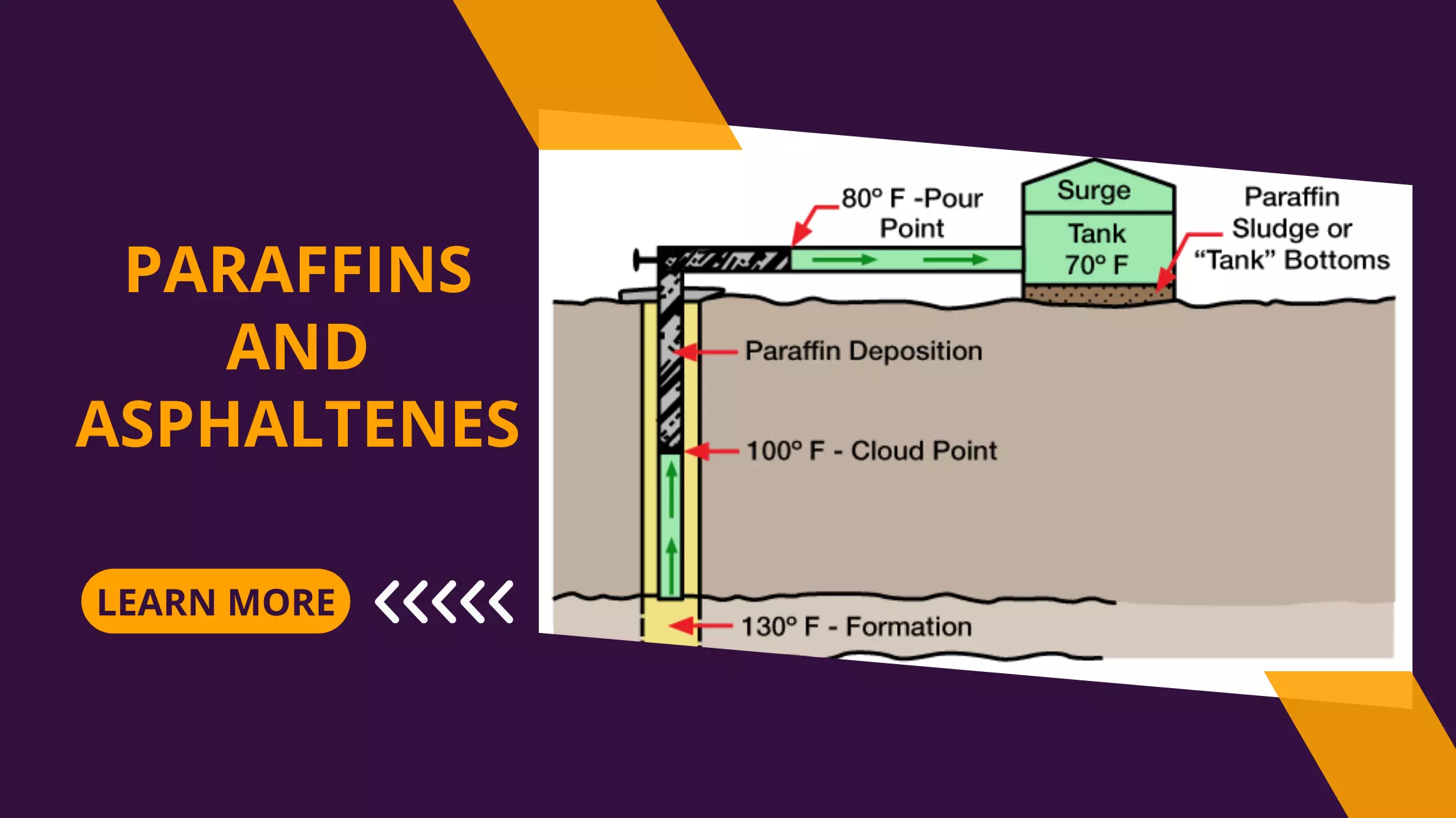
Tubing in the well – if it is known to be clean, or it can be cleaned in place – can be used to inject acid. If the tubing has considerable scale buildup or if paraffin and/or asphaltenes have accumulated inside, the tubing should be bypassed with a concentric string or replaced with a special treating string. If a treatment string is used, however, pipe dope application to the threads should be closely supervised. Excessive pipe dope can cause perforation plugging and less than desirable acidizing results. The use of plastic-coated tubing eliminates the need to clean or “pickle” the tubing with acid prior to acid placement.
Wellbore Geometry: The mechanical aspects of acid placement must be selected according to well conditions and wellbore geometry.
In wells with long multiple-producing intervals, zone coverage control is needed. The most effective treatment is with an opposed cup packer (wash tool). It can distribute the HCl preflush over every foot of zone, followed by a similar run with the HF acid stage and then the overflush. This technique ensures that every part of the perforated interval is treated.
Another way to acidize the productive zone effectively is with a retrievable bridge plug and squeeze packer positioned, respectively, below and above selected perforations.
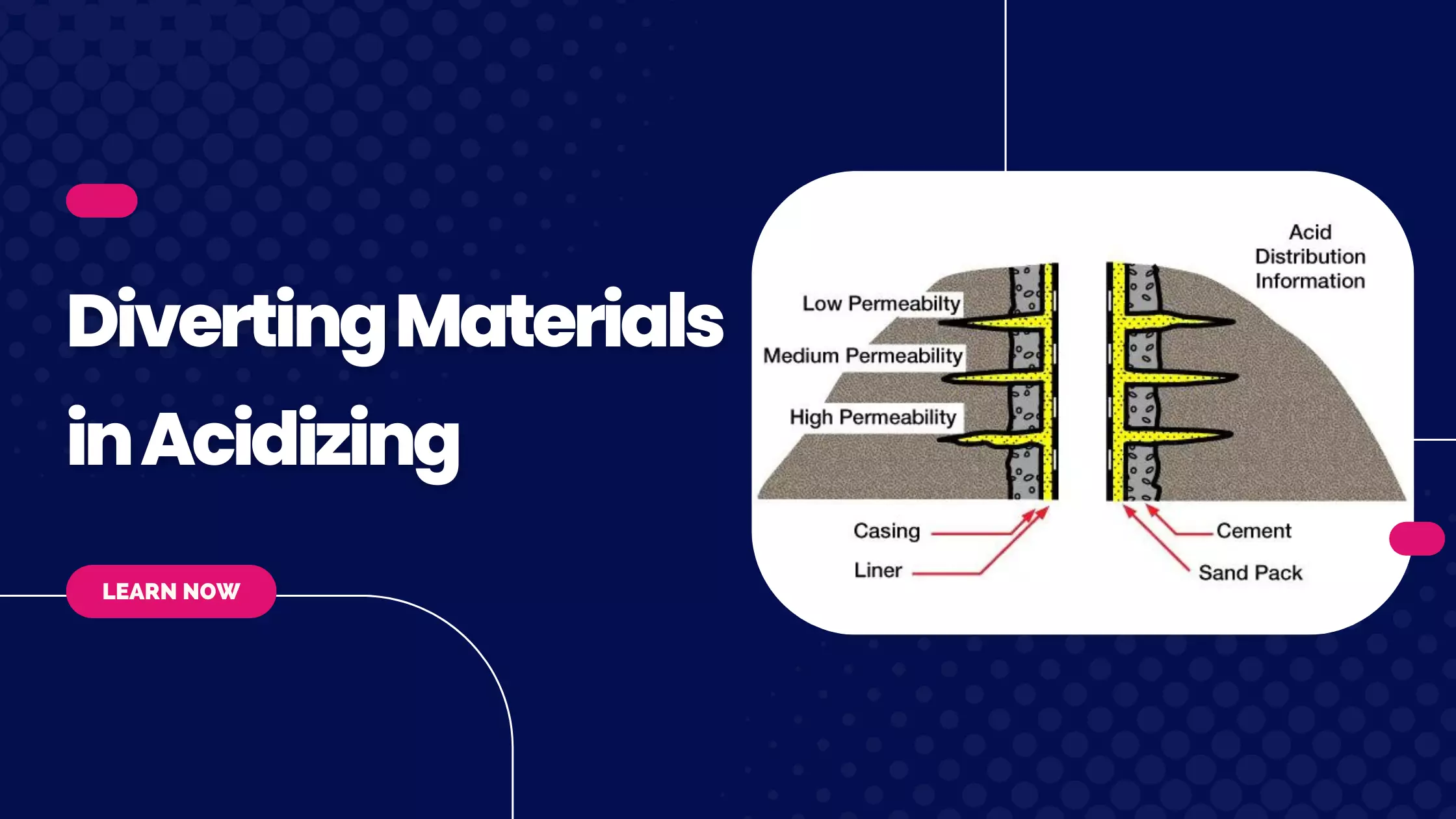
Moreover, successful use of these techniques requires an excellent cement job. A cement bond log (CBL) run after primary cementing can help to show whether zone isolation has truly been achieved. If there is some question about cement job integrity in the vicinity of the intended perforations, diverting materials should be considered.
Tubular Cleanup Fluid: If new tubing is in the well, the safest way to help prevent formation damage is to pickle the pipe with acid containing large quantities of iron-retention additives, and to circulate the acid out of the well. Xylene or hydrocarbon phase should be used as a preflush for the removal of pipe dope and varnish, which can plug perforations. A suggested tubular cleanup procedure includes 15% HCl to remove the mill scale which is in most new tubular goods. Sequestering additives maintain the dissolved iron in solution and the penetrating, nonionic surfactant helps the acid contact the pipe and scale after the xylene. This cleaning and pickling process helps prevent the deposition of debris into the formation during the stimulation treatment.
Selecting Stage Volumes: The engineer can better select sandstone acidizing stages and stage volumes by analyzing the well.
- Formation Injection: A hydrocarbon preflush should be placed in the formation ahead of the HCl preflush if crude oil/acid incompatibility exists. Should a problem crude and calcium coexist in the reservoir, an aromatic acid dispersion should be squeezed into the formation to remove both calcium carbonate and paraffin/asphaltenes.
- Preflush: The volume of preflush fluid should be large enough to accomplish two goals: (1) dissolve the calcium carbonate contained in the zone contacted by unreacted HF and (2) provide sufficient fluid at least 2 ft from the wellbore to serve as an adequate barrier between the reacted HF and formation brine. Therefore, the volume and strength of the preflush is somewhat contingent on the calcium carbonate content of the formation. HF reaction products (H2SiF6, etc.) are somewhat compatible and soluble in the presence of calcium carbonate; hence, it is only necessary to remove the calcium carbonate from the zone contacted by HF to prevent precipitation of calcium fluoride.
- HF Acid: The HF stage should be designed for at least two hours (preferably four hours) of contact time around the wellbore.
- Over flush: The overflush should be designed to displace the HF to a radius of 3 to 5 ft around the wellbore, or the overflush volume should at least equal the HF stage. This pushes hydrous silica and other insolubles out to a safe distance, minimizing the damaging effects from these solids during subsequent production.
Stage volumes for the acid treatment are determined by the allowable injection rate in 8 to 10 hours of daylight acidizing time. First priority is the overflush, second is the 2 to 4 hours of HF contact time, and third is total acid pumping time. Nitrogen or CO2 can be added to the various stages, depending on reservoir pressure and the anticipated difficulty in recovering the treatment.