Related Articles


Full Diameter Core Analysis
Routine Analysis
Full diameter core analysis enables the testing of those heterogeneous rocks with complex lithology (Figure 1).
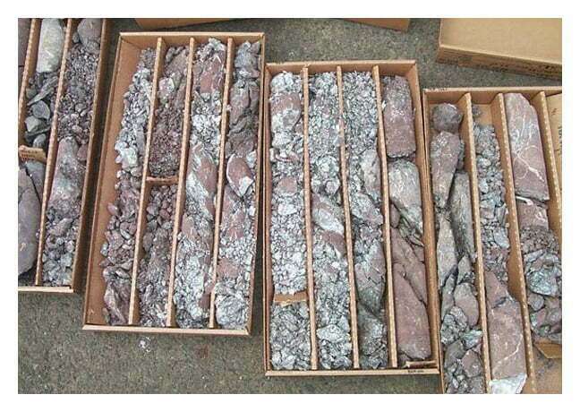
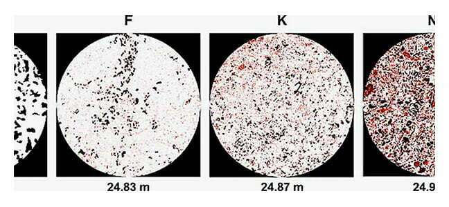
Heterogeneous carbonates (Figure 2), and fissured, vugular formations are often unsuitable for plug analysis alone, as the plugs may not be sufficiently representative of the multi-scale heterogeneity in the pore geometry and the rock texture. Full diameter core samples may need to be used in an attempt to encompass the scale of heterogeneity.
Analysis of these rocks requires samples that are as large as can be obtained, so that the pore spaces are relatively small compared to the bulk volume of the samples. Lithology and pore space in carbonates may be highly variable, and the porosity can exist as micro-porosity, intergranular, vuggy and fracture porosity or a combination of all these four types of porosity. The full diameter technique does not differentiate between the contributions made by each of these types of porosity, but generates a single porosity value that includes all pore type combinations.
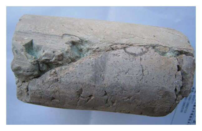
Samples in the form of a cylinder up to 10 inches (25 cm) long and from 2.5 inches (6.2 cm) to 5 inches (12.5 cm) in diameter are often used. Data generated include Boyle’s law porosities, using helium as the saturating medium. Two horizontal permeability values are determined by flowing fluid across the core diameter. When fractures (cracks or surfaces of breakage within a rock) or vugs (cavities, voids or large pores in a rock that are commonly lined with mineral precipitates) are present (Figure 3) , one of the permeability measurements is visually oriented through the more permeable direction of the core, and the second permeability is at right angles to this measurement. In this manner, the effect of vugs or fractures on horizontal permeability is indicated. Vertical permeabilities are also typically analyzed.
A method for differentiating between the matrix properties and the full diameter core data affected by fracture or vugular porosity is to drill and test plugs selected from the more uniform segment to the rock matrix. A comparison of such data using this type of test is shown in Table 1. Matrix properties are important because they control initial water content, and thus the matrix hydrocarbon saturation.
| Property | Plug data | Whole core data |
|---|---|---|
| Air Permeability, mD | 0.1 | 69 |
| Porosity, % | 10.3 | 11.3 |
| Residual oil,% pore space | 14.7 | 17.1 |
| Total water, % pore space | 24.6 | 37.7 |
Table 1: Comparison of Plug and Whole Core Data on Micro-fractured Oil Producing Sandstone Samples
Pressure Core Analysis
A pressure core barrel is used to maintain the reservoir pressure on the core throughout its recovery to the surface. A pressure core barrel is typically frozen at the wellsite and then cut into three foot, or one meter, lengths before shipment to the laboratory for analysis in a frozen condition.
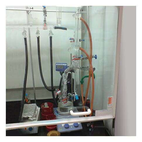
The analysis of full diameter pressure cores generally follows the procedures normally used in routine analysis, with some modifications. The frozen full diameter samples are cut in the form of a cylinder and then placed in specialized, airtight containers where they thaw, so that the fluids expulsed from the core can be collected and measured. The cores are subsequently moved through the Dean-Stark apparatus (Figure 4). The Dean-Stark apparatus (or Dean-Stark receiver, or distilling trap, or Dean-Stark head) is laboratory glassware used in chemistry to collect water (liquids) from a reactor. The apparatus is used in combination with a reflux condenser and a batch reactor for continuous removal of the water that is produced during a chemical reaction performed at reflux temperature.
After removal from the Dean-Stark apparatus, pressure core samples should be further cleaned in a toluene-CO2 pressure fluxer. This requires that the samples be placed in a surgical stocking so that any rock fragments that come loose from the core during cleaning are retained. This is necessary because the residual oil saturation value that is obtained from the analysis is at least partially dependent upon the weights taken during the analytical process.
The airtight vessel in which each frozen core is placed is evacuated for a short period of time to remove all the air surrounding the core. As the rock thaws, the gas that evolves from the residual oil saturation escapes from the core and is retained within the vessel surrounding the core. The volume of this gas is measured and its composition determined by a chromatograph. A gas chromatograph measures the content of various gas components in a sample. The sample solution injected into the instrument enters a gas stream which transports the sample into a separation tube known as the “column.” Helium or nitrogen is used as the carrier gas. The various gas components are separated inside the column, and the detector measures the quantity of the components that exit the column. To measure a sample with an unknown concentration, a standard sample with known concentration is injected into the instrument. The standard sample peak retention time (appearance time) and area are compared to the test sample to calculate the concentration.
A gas chromatograph is useful if exotic gases have been injected into the formation, and it is essential to know what parts of the reservoir have been swept by this injected gas. The surface volume equivalent of the residual oil saturation present in the core at reservoir conditions is determined by summing the oil that is expulsed during the thawing process with the oil that is subsequently removed during the Dean-Stark and toluene-CO2 cleaning.
The handling and analysis of pressure cores can be summarized as follows:
- The metal barrel is milled down its length and the core is removed.
- The frozen drilling mud is chipped from the core surface.
- The core is cut into full diameter cylinders.
- The core is weighed, and then thawed in evacuated glass chambers.
- The oil, water and gas expulsed are collected, and the gas volume is determined. The composition of the collected gas is measured.
- The core samples are cleaned in a Dean-Stark apparatus, which generates water saturation data and partial data for the determination of the residual oil.
- The core is cleaned in a toluene-CO2 extractor.
- A Boyle’s law porosity value is determined, as well as the horizontal and vertical permeability. The water and residual oil saturations are calculated, and a correction for oil shrinkage is applied.
- At selected locations, plugs from sections of the frozen rock which are not used in full diameter analysis are drilled vertically down the center line of the core. The water that is present in the centermost plug and in the surrounding doughnut is analyzed for the presence of tracers previously added to the filtrate, which provides some insight into core flushing.
Sponge Core Analysis
Full diameter analysis of core samples recovered from within the sponge barrel continues as usual once the core has been removed from the barrel. The sponge itself is cut from the core barrel, and the fluids it contains are extracted using a vacuum retort technique. Both the oil and water volumes within the sponge are measured. Table 2 shows the residual oil saturation data for the core alone, and for the core plus sponge, for a specific field example. Note that the contribution of the sponge is variable and may be significant.
| Depth Feet | Core residual oil % pore space | Sponge residual oil % pore space | Total (sponge plus core) residual oil % pore space |
|---|---|---|---|
| 4636 | 23.1 | 0.8 | 23.9 |
| 4637 | 23.1 | 0.8 | 23.9 |
| 4638 | 21.7 | 8.3 | 30.0 |
| 4639 | 20.4 | 10.0 | 30.4 |
| 4640 | 28.7 | 7.0 | 35.7 |
| 4641 | 22.1 | 6.2 | 28.3 |
